
2-MHz Frequency Standard With Dividers

The oscillator circuit described operates efficiently within the frequency range necessary for calibration purposes. The use of a 2MHz crystal oscillator provides a stable frequency source, while the 100kHz crystal serves as a secondary reference, allowing for versatile frequency division. The isolation amplifier plays a crucial role in ensuring that the output from the crystals does not affect the performance of the counter, maintaining signal integrity.
The 7490 decade counter is integral to this design, as it allows for the division of the oscillator frequencies into lower frequencies that can be utilized in various applications. The division ratios of 100, 20, 10, 4, and 2 enable a range of output frequencies that can be adjusted according to the needs of the user. This flexibility is particularly beneficial in calibration tasks, where different frequency references may be required.
The grounding of pin 1 to the common terminal is essential for the proper operation of the circuit, ensuring that all components share a common reference point, which minimizes noise and potential errors in frequency readings. The reset gates located at pins 7, 6, 3, and 2 allow for easy resetting of the counter, facilitating quick adjustments and ensuring accurate measurements.
Overall, this oscillator circuit is a valuable tool for electronics enthusiasts and professionals alike, providing a reliable means for frequency calibration across a variety of devices. The rich harmonic content up to 144MHz further enhances its utility, making it suitable for a wide range of applications in the field of electronics.This is an oscillator circuit that can be used for calibrating frequency counters, amateur receivers and frequency meters. This circuit is called 2MHz standard with dividers circuit. This circuit uses two crystals, 100kHz and 2 MHz. Here is the schematic diagram of the oscillator part of the circuit: This circuit is then can be combined with two
7490 decade counter, that is fed by the crystals through isolation amplifier. This circuit also divide the frequencies by 100, 20, 10, 4, and 2 for each oscillator. All frequencies is usable and rich in harmonics through 144MHz. For all mode of operation, the ground at pin 1 must be tied to common terminal. The counter reset gates at pins 7, 6, 3, and 2. We aim to transmit more information by carrying articles. Please send us an E-mail to wanghuali@hqew. net within 15 days if we are involved in the problems of article content, copyright or other problems. We will delete it soon. 🔗 External reference
Related Circuits
The lf555afosc1.pdf file download contains a diagram with annotations for a Sub-Tone (CTCSS or "PL") Oscillator, designed using the well-known 555 timer IC configured for astable multivibrator operation. The component values are selected to position the tone range near...
This frequency doubler utilizes a CMOS quad two-input NAND gate package, specifically the 4011 type. The core of the frequency doubler includes an inverter (IC1B) along with two differentiating networks composed of resistors (R1, R2) and capacitors (C1, C2)....
A simple variable frequency oscillator utilizing a 555 timer IC to generate a square wave frequency that can be adjusted using a potentiometer. The circuit operates primarily on the principles of astable multivibrator configuration using the 555 timer IC, which...
The circuit utilizes a 555 timer configured as a multivibrator, where the oscillation frequency is determined by resistors R1, R2, and capacitor C1. The frequency formula is given by fo = 1.443 / ((R1 + R2) * C1). The...
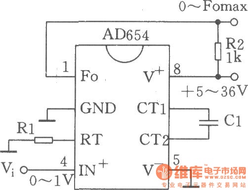
The circuit depicted is a low-cost voltage frequency converter (VFC) utilizing the AD654 component. By connecting the required components, Rl and Cl, as shown in the figure, a functional VFC application circuit can be established. The supply voltage can...
The circuit was designed to generate an oscillator that operates at low frequencies, intended for use in electronic music production, experimentation, and testing. The low-frequency oscillator (LFO) circuit typically consists of several key components, including resistors, capacitors, and an operational...