
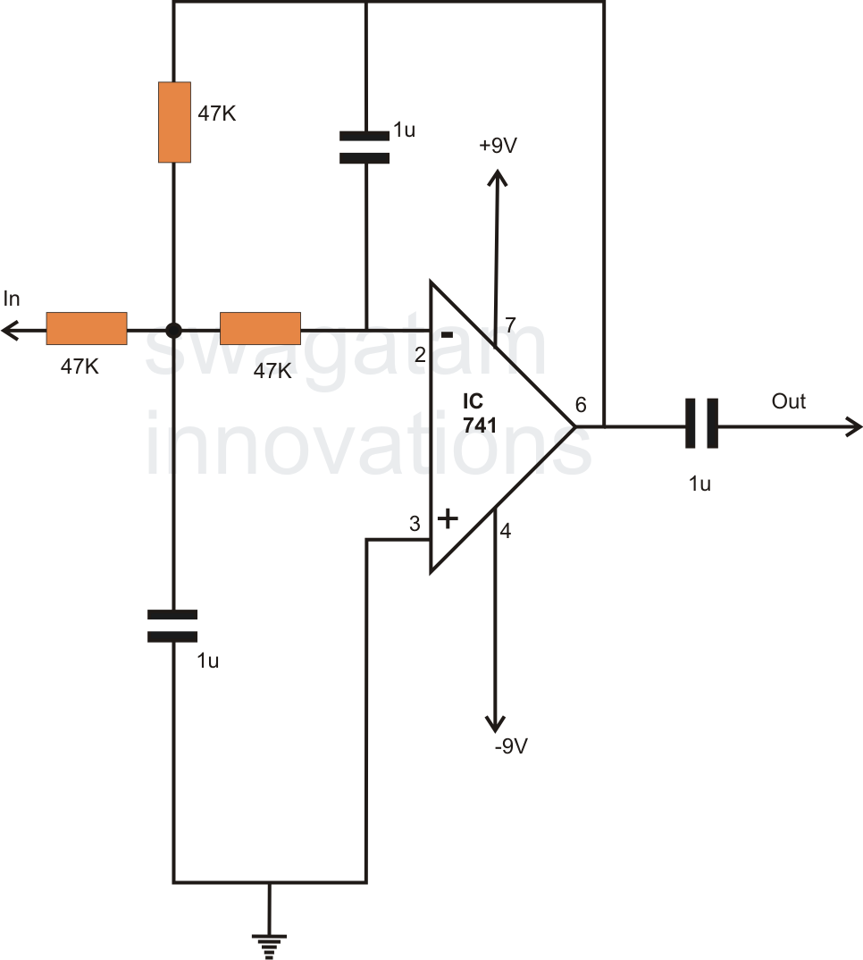
very simple oscillator 7700 Hz

The circuit simulation involves utilizing NI Multisim, a powerful software tool designed for electronic circuit design and analysis. The primary function of the oscillator in this circuit is to produce a stable waveform, which is essential for timing applications in various electronic devices. The stability of the waveform is critical, as it ensures consistent performance in digital circuits.
In order to save the simulation results, users must access the source code within the Multisim environment. This feature allows for the documentation and reuse of circuit designs and simulation data, which is particularly beneficial for iterative design processes or educational purposes.
The choice of clock source is a fundamental aspect of circuit design. Different devices may require specific types of clock sources, such as crystal oscillators, RC oscillators, or PLLs (Phase-Locked Loops), depending on the frequency stability and accuracy needed for the application. Understanding the characteristics and limitations of these clock sources is vital for optimizing circuit performance and ensuring compatibility with other components in the system.
In conclusion, the successful simulation of the circuit in NI Multisim version 11 hinges on understanding the oscillator's role in generating stable waveforms and the importance of selecting the appropriate clock source for the specific application.for simulation this circuit you must have NI multisim produced by National Instrument When oscillator nearing stable Waveform oscillator if you want save file go to source code and you need multisim ver11 How its work exactly? you must know this fact , most device have clock source ,and clock source they used depend. 🔗 External reference
Related Circuits
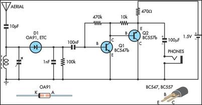
This circuit is essentially an amplified crystal set. The inductor could be a standard AM radio ferrite rod antenna while the tuning capacitor is a variable one. The described circuit operates as an amplified crystal radio receiver, which utilizes a...
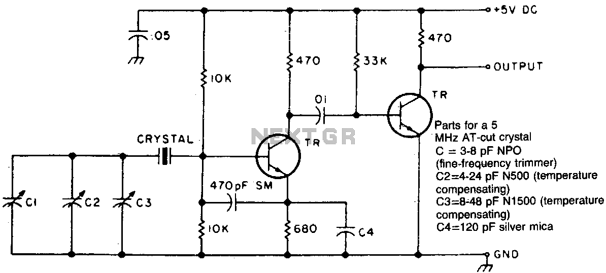
Two different negative-coefficient capacitors are blended to produce the desired change in capacitance to counteract or compensate for the decrease in frequency of the "normal" AT-cut characteristics. The circuit utilizes a combination of two negative-coefficient capacitors to achieve a specific...
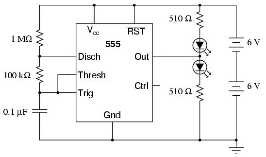
An oscilloscope is useful for analyzing the waveforms produced by this circuit, although it is not essential. An audio detector serves as a valuable piece of test equipment for this experiment, particularly if an oscilloscope is unavailable. The "555"...
The above pictured schematic diagram is just a standard constant current model with a added current limiter, consisting of Q1, R1, and R4. The moment too much current is flowing biases Q1 and drops the output voltage. The output...
In electronics, filter circuits are primarily used to restrict the passage of certain frequency ranges while allowing other frequency bands to proceed to subsequent stages of the circuit. A high-pass filter circuit permits only frequencies that exceed a specified...
This low-cost short-wave transmitter is tunable from 10 to 15 MHz using a ½J gang condenser VC1, which sets the carrier frequency in conjunction with inductor L1. Frequency trimming is achieved with VC2. The carrier signal is amplified by...