
VFO stabilization with 2N4416
The described circuit involves a variable frequency oscillator (VFO) utilizing a coil constructed with approximately 25 turns of #28 gauge wire wound on a T-44-6 ferrite core. The coil is strategically tapped at around 5 turns, allowing for adjustable inductance, which is crucial for tuning. The tuning process may require slight adjustments based on the specific components used in the circuit. The application of Q dope, a type of adhesive that enhances the quality factor of the coil, is recommended to stabilize the turns after they have been positioned to achieve the desired tuning range.
The circuit is implemented on a single-sided etched printed circuit board (PCB), designed for compactness and effective shielding. The PCB is integrated into a shield box, which serves to minimize interference and maintain signal integrity. Connection to the tuning capacitor is achieved by soldering directly to the stator pins, ensuring a solid electrical connection. A small bead of solder is also applied to ground the assembly, providing a reference point for the circuit.
The performance of the VFO may be impacted by component selection. In particular, the use of NP0 (C0G) ceramic capacitors is noted, as they are known for their stability over temperature and voltage variations. However, it is mentioned that the VFO exhibited drift, characterized by a frequency decrease of approximately 100 Hz per hour, indicating potential issues with component stability or circuit design that may require further investigation and adjustment to achieve reliable operation.The coil is about 25 turns #28 wire on a T-44-6 core, tapped at about 5 turns. I'm too lazy to open my VFO and count it for you -- besides, you'll probably have to tweak it yourself with your available components. Once the turns are squeezed to the right place to adjust the tuning range, a bit of Q dope holds them in place.
This is built on a one-sided etched board, which fits neatly into the PC board shield box and is soldered right to the stator pins of the particular tuning capacitor, with just a little bead of solder to tack it to ground. When I started with the Lewallen "Optimized QRP Transceiver" VFO, it never really settled down for me in various iterations. It always kept drifting down, down, down about 100 Hz/hour, never stopping, even when using brand new NP0 Panasonic chip capacitor
🔗 External reference
Related Circuits
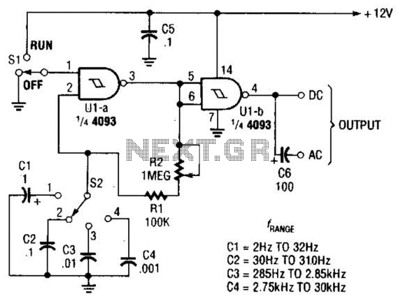
The circuit illustrated operates within a frequency range of 2 Hz to 30 kHz. Additionally, R2 is configured as either a linear or logarithmic potentiometer. The circuit is designed to accommodate a wide frequency spectrum, making it suitable for various...
This amplifier circuit integrates the LT1010 with a fast discrete stage and employs an LT1008-based DC stabilization loop. It features a differential stage that operates in a single-ended configuration. The described amplifier circuit is designed to enhance signal amplification while...

This VFO circuit operates within a frequency range of 2.13 to 2.58 MHz and is designed for integration with an external mixer to heterodyne the signal to the desired frequencies. Coil specifications are provided in the parts list. The...
The three schematics illustrate three building blocks for a 10-meter SSB transmitter. These blocks can also be utilized independently as circuit modules for other transmitters. The VFO board incorporates an FET transmission oscillator, with the VFO signal being mixed...
Almost any 2x16 character LCD module with Hitachi HD44780 controller chip will work. The LCD pin numbers on the schematic are not valid for all LCD modules. Please check the actual signal names on your particular LCD module. The...
The inductor is made by winding 8 turns of #24 insulated solid copper wire on a 5 mm screwdriver. I used a conductor from a piece of category 5 quad twisted pair, left over from wiring the house with...
Warning: include(partials/cookie-banner.php): Failed to open stream: Permission denied in /var/www/html/nextgr/view-circuit.php on line 713
Warning: include(): Failed opening 'partials/cookie-banner.php' for inclusion (include_path='.:/usr/share/php') in /var/www/html/nextgr/view-circuit.php on line 713