
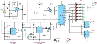
VHF remote control

The remote control system utilizes a VG40T transmitter and a VG40R receiver, which operate on a frequency of 300 MHz. The compact transmitter module dimensions of 34 mm x 29 mm x 10 mm allow for easy integration into various applications. It operates with a 9-volt PP3 battery, providing a transmission range of up to 15 meters without requiring an external aerial.
The VG40R receiver module, measuring 45 mm x 21 mm x 13 mm, can be configured for multiple relay control scenarios. The first configuration allows for momentary activation of a relay. Upon pressing the transmitter switch, a positive voltage is generated at the VG40R output pin, which biases a relay driver transistor. The relay engages while the switch is held down and releases upon switch release, allowing for control of electrical or electronic loads through normally open (N/O) relay contacts.
For timed relay activation, the second configuration employs an IC 555 configured as a monostable multivibrator. Pressing the transmitter switch momentarily biases the transistor, which then triggers the IC 555. The relay remains engaged for a user-defined period, adjustable through timing components, providing flexibility from a few seconds to several minutes.
Lastly, the system can be set up for toggle action using a combination of the IC 555 and a decade counter (4017). The 4017 is configured as a flip-flop, with the Q0 output controlling the relay. Pressing the transmitter switch alternately toggles the relay state, allowing for easy on/off control of connected loads. The timing for the monostable multivibrator can be set to approximately one second to ensure quick responsiveness.
For optimal performance, it is recommended to use a short length of shielded wire between the VG40R output and the rest of the circuit. Additionally, housing the transmitter within a non-metallic case, such as plastic, is essential to maximize operational range and minimize signal interference.A few designs for remote control switches, using VG40T and VG40R remote control pair, are shown here. The miniature transmitter module shown in Fig. 1, which just measures 34 mm x 29 mm x 10 mm, can be used to operate all remote control receiver-cum-switch combinations described in this project.
A compact 9-volt PP3 battery can be used with the transmitter. It can transmit signals up to 15 metres without any aerial. The operating frequency of the transmitter is 300 MHz. The following circuits, using VG40R remote control receiver module measuring 45 mm x 21 mm x 13 mm, can be used to: (a) activate a relay momentarily, (b) activate a relay for a preset period, (c) switch on and switch off a load. To activate a relay momentarily (see Fig. 2), the switch on the transmitter unit is pressed, and so a positive voltage is obtained at output pin of VG40R module. This voltage is given to bias the relay driver transistor. The relay gets activated by just pressing push-to-on micro switch on the transmitter unit. The relay remains energised as long as the switch remains pressed. When the switch is released, the relay gets deactivated. Any electrical/electronic load can be connected via N/O contacts of the relay. To activate a relay for a preset period (refer Fig. 3), the switch on the transmitter unit is pressed momentarily. The transistor gets base bias from VG40R module. As a result the transistor conducts and applies a trigger pulse to IC 555, which is wired as a monostable multivibrator.
The relay remains activated till the preset time is over. Time delay can be varied from a few seconds to a few minutes by adjusting timing components. To switch on and switch off a load (refer Fig. 4), a 555 IC and a decade counter 4017 IC are used. Here the 4017 IC is wired as a flip-flop for toggle action. This is achieved by connecting Q2 output to reset terminal while Q1 output is unused. Q0 output is used for energising the relay. The relay is activated and deactivated by pressing the transmitter switch alternately. So, to activate the load, just press the transmitter switch once, momentarily. The relay will remain activated. To switch off the relay, press the transmitter switch again. This process can be repeated. Time delay of monostable multivibrator is set for about one second. Note: Short length of shielded wire should be used between VG40R receiver module output and the rest of the circuit. The transmitter with 9V battery must be housed inside a nonmetallic (say, plastic) cabinet for maximum range of operation.
🔗 External reference
Related Circuits
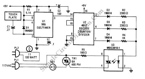
This circuit can switch two or more devices on and off in response to a series of rapid handclaps. The claps are picked up by an electret microphone. The circuit operates by utilizing an electret microphone, which serves as the...
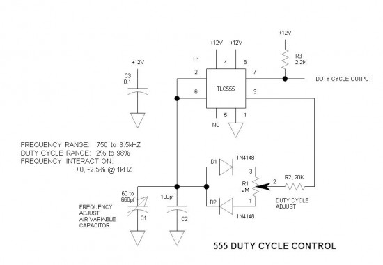
A simple oscillator circuit that varies the duty cycle over a wide range without affecting the frequency. It is a variation of the simple 555 astable oscillator. The use of an air-variable capacitor for frequency control is innovative. When...
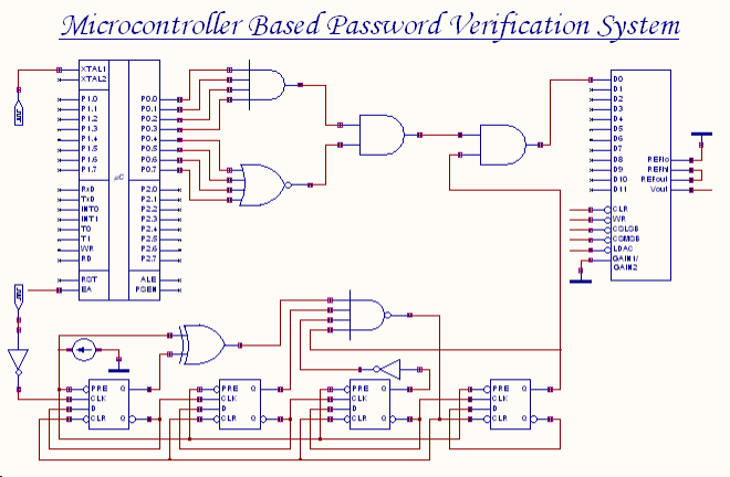
An 8-bit password serves as the input to this system. The password entered by the user is compared with the actual password, which is set in the microcontroller through a microprogram. The outcome of this comparison process generates an...
This is a three-mode lamp dimmer circuit with touch control. This circuit can be used to control a lamp in three operation modes: dim, off, and bright. A NE555 timer is utilized in the design. The three-mode lamp dimmer circuit...
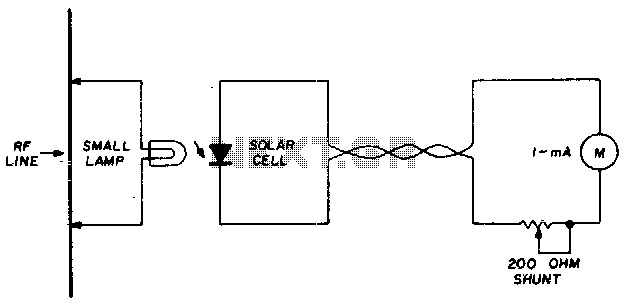
A suitable pilot lamp is illuminated by a small sample of RF energy and energizes an inexpensive solar cell; the DC current generated by the cell serves as a measure of relative RF power and may be routed to...
A DC motor from an old personal stereo cassette player has been utilized in this circuit, which provides control over both the speed and direction of the motor. The circuit employs PWM waveforms to drive a MOSFET H-bridge, as...