
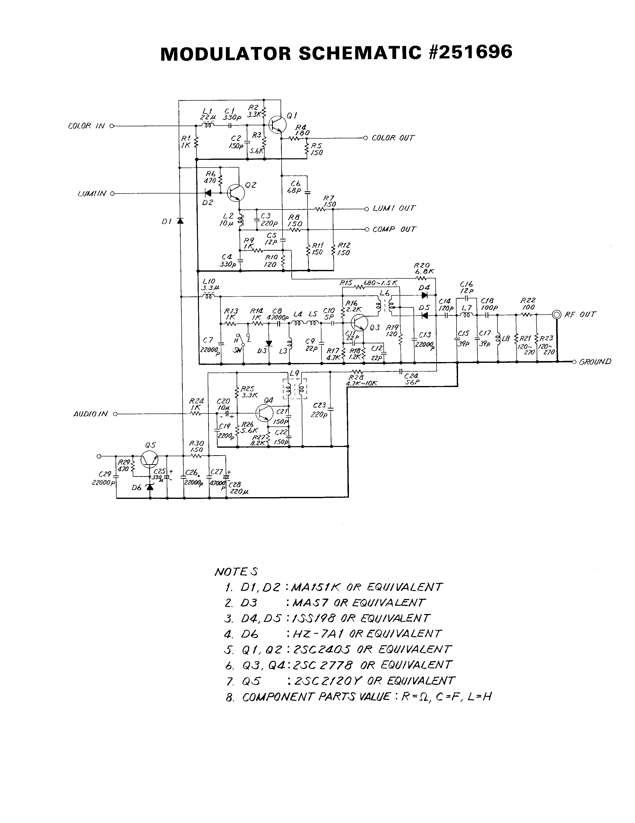
VHF Video Sender/Transmitter

The described circuit functions as a VHF video transmitter, utilizing amplitude modulation (AM) to transmit video signals effectively. The design allows for operation across two distinct frequency ranges: channels 7 to 13 and channels 14 to 29. The modulation technique employed is crucial for the transmission of video signals over the VHF band, which is commonly used for television broadcasting.
In the modulator section, inductors L1 and L2 play a significant role in determining the operating frequency of the circuit. For channels 7 to 13, the inductors are configured with three turns of #22 gauge wire wound on a 3/16 inch diameter form. This configuration results in a higher inductance value, which is necessary for the lower frequency range of these channels. Conversely, for channels 14 to 29, L1 and L2 are adjusted to two turns of #22 gauge wire on the same form. This reduction in the number of turns decreases the inductance, allowing the circuit to operate effectively at the higher frequencies of this channel range.
The video signal input is modulated onto a carrier frequency using AM, which involves varying the amplitude of the carrier wave in accordance with the video signal. This method is effective for transmitting visual information, as it allows for the preservation of the original video quality over the airwaves.
The overall design of the circuit emphasizes simplicity and efficiency, making it suitable for various applications in video transmission within the VHF band. Proper tuning and alignment of the inductors, along with careful selection of other components in the circuit, are essential for optimal performance and signal clarity.This circuit is a powerful video sender in VHF band. The modulator section is designed to operate on either channels 7 to 13 or 14 to 29. For channels 7 to 13, L1 and L2 are 3 turns of #22 wire wound on a 3/16 inch form. For channels 14 to 29, L1 and L2 are 2 turns of #22 wire wound on a 3/16 inch form. Video signal is modulated as AM. 🔗 External reference
Related Circuits
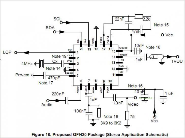
MC44BS374CA: PLL Tuned UHF and VHF Audio Video High Integration Modulator MC44BS374CA The MC44BS374CA Audio and Video Modulator is for use in VCRs, set-top boxes, and similar devices. By Freescale Semiconductor, Inc The MC44BS374CA is a highly integrated audio and...
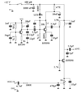
This video transmitter circuit operates on the UHF channel frequency of 470-580 MHz, specifically channels 21-34. It can transmit video signals over distances ranging from 30 to 100 meters when using a cable length of 10 to 20 cm....
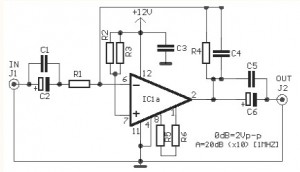
The video amplifier circuit utilizes the LM359 integrated circuit, which is a dual, high-speed, programmable current mode (Norton) amplifier. This circuit is suitable for general-purpose video amplification applications. The LM359 is designed to operate as a high-speed amplifier, making it...
This modification involves swapping the C64 audio/video connector with a standard connector that accommodates a regular S-video cable, while utilizing the RF modulator RCA jack for audio output. The use of standard connectors simplifies the process and minimizes complications. This...
A 555 timer and a dual 556 timer are used to generate a basic video signal, as illustrated in the schematic. The first timer operates in astable mode, producing synchronization pulses with a period ranging from 4.7 to 8...
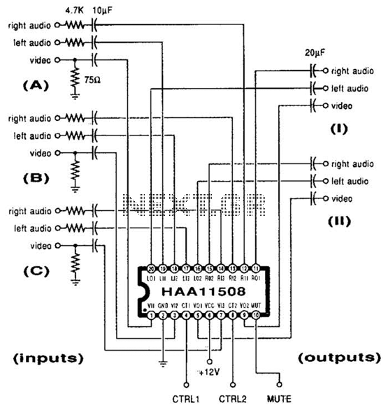
This channel selector selects video and stereo audio from any one of three different sources. The circuit should be constructed on a PC board with plenty of ground plane to minimize noise. The channel selector circuit is designed to facilitate...