
vhfuhf tv modulator

The TV modulator circuit operates by generating a carrier frequency that can be modulated with video signals, allowing the transmission of video content to standard television receivers. The oscillator, based on the BFR91 transistor, is designed to maintain a stable frequency output while being modulated. The selection of components surrounding the transistor is critical; they must be optimized for high-frequency operation to minimize signal distortion and ensure efficient modulation.
The Schottky diodes, Dl and D2, are integral to the circuit as they facilitate the generation of harmonics necessary for effective transmission. Their fast switching capabilities ensure that the harmonics produced are strong and cover a wide frequency range, which is essential for compatibility with various TV tuners.
The modulation depth control, Pl, allows for fine-tuning of the amplitude of the modulated signal, enabling the user to adjust the signal strength according to the requirements of the transmission environment. The second control, P2, adjusts the direct current level of the oscillator, which can impact the overall performance of the modulation process.
Power supply considerations are also important for the operation of this circuit. An unstabilized 8.30 V supply can be used, but a stabilized 5 V supply is preferable for consistent performance. This can be conveniently sourced from a computer's power supply, which is widely available and provides a clean voltage source, thereby eliminating the need for additional voltage regulation components.
In summary, this TV modulator circuit exemplifies a compact and efficient design for transmitting video signals to television receivers, utilizing high-frequency components and precise modulation controls to achieve optimal performance.The electronic circuit is a TV modulator that is really no more than a transmitter. It is a very small transmitter, admittedly, but none the less that is what it is. What does a modulator actually do In general -and this design is no exception to the rule - it is a simple oscillator that generates a frequency somewhere in the VHF or UHF region. T he oscillator is modulated with the video signal and the modulated carrier wave thus generated is fed into the TV set`s aerial input via a cable. Then all that remains to do is tune the TV to the correct frequency. The crystal oscillator is based on a very fast HF transistor, Tl (BFR91), which performs the amplitude modulation.
Apart from this there is little to be said about the oscillator except, perhaps, that it is essential to use the correct values for the components surrounding Tl. This is, of course, simply common sense in this sort of HF circuit. The harmonics generator is formed by two Schottky diodes, Dl and D2. These diodes must switch very quickly in time with the 27 MHz signal so they provide strong harmonics up into the gigahertz range.
The modulation depth can be set with Pl, while the oscillator`s d. c. value can be varied by means of P2. The combination of these two presets enables either positive or negative amplitude modulation to be selected. This is essential as the harmonics produced vary in this respect. We will discuss the calibration of Pl and P2 later in this article. The power for the circuit can be provided by either an unstabilized 8. 30 V or a stabilized 5 V. The latter could be taken from a computer`s power supply and in this case ICI is not needed. 🔗 External reference
Related Circuits
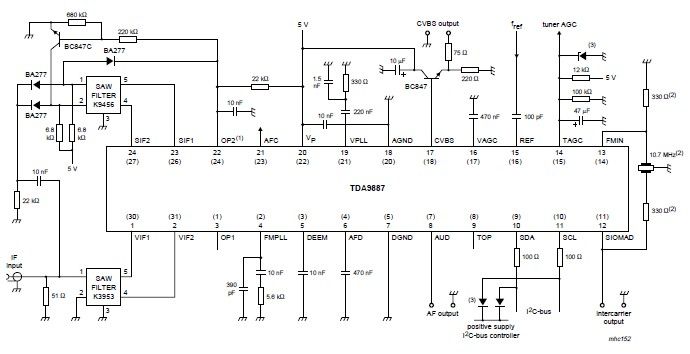
The integrated circuit (IC) is a multistandard vision and sound intermediate frequency (IF) phase-locked loop (PLL) demodulator that operates without the need for alignment. It supports multiple standards, including PAL, SECAM, and NTSC, and is capable of processing both...
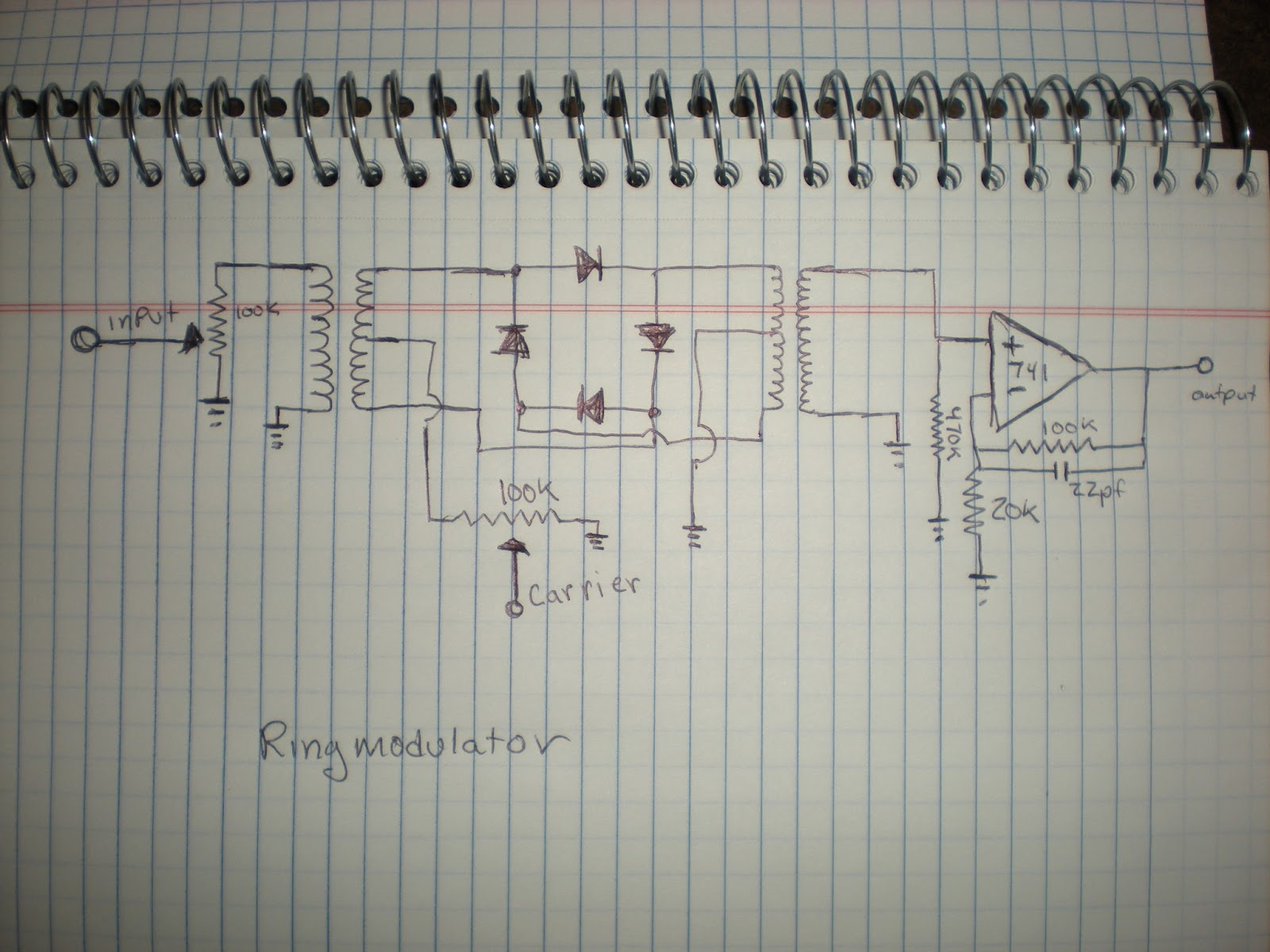
The author has created various modules since the last blog post and has gained a deeper understanding of electronics, particularly with operational amplifiers (Op Amps). The author does not guarantee the designs shared, as they are an amateur learning...
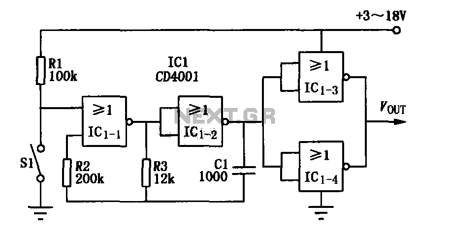
The core elements of this circuit are the second four-input NOR gate terminal IC CD4001. The entire circuit features a simple structure, with fewer components, making it easy to construct, particularly for remote control transmitters or carrier modulation transmission....
Although there is a need for an integrated circuit (IC), the interface between the modulator and audio-video signals has not yet been developed as an IC. This is primarily due to the complexity of such a design, the variations...
With the impending shutdown of the 405-line transmitter network, individuals with collections of early television sets must find new methods to supply them with appropriate signals. Regardless of the scheme implemented, a method for converting baseband audio and video...
The circuit depicted in the figure is a 567 FM demodulation circuit. The FM signal enters through pin 3, and the demodulated output signal is available at pin 5. The center frequency of the FM signal that the circuit...