
Video Fader Circuit

Fading a video signal involves a careful adjustment of both the luminance and chrominance components while maintaining the integrity of the synchronization signals. Simply reducing the amplitude of the composite video signal can lead to a situation where the sync pulses become too weak, causing potential issues in the display of the video.
To implement a proper fading circuit, a more sophisticated approach is required. This can be accomplished using a dedicated video fading circuit that utilizes operational amplifiers (op-amps) configured to handle the specific frequency ranges of the video signal.
A typical schematic for a video fading circuit would include the following components:
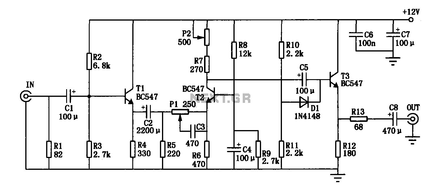
1. **Input Stage**: The composite video signal is fed into the circuit, typically through a BNC connector. This signal carries both the video information and synchronization pulses.
2. **Buffering**: An initial op-amp buffer may be used to isolate the input signal from the fading circuit. This ensures that the loading effect does not alter the signal characteristics.
3. **Attenuation Control**: A variable resistor (potentiometer) can be used to adjust the level of attenuation applied to the signal. This potentiometer should be connected in a voltage divider configuration with feedback to the op-amp to maintain the signal integrity.
4. **Synchronization Preservation**: To ensure that the sync pulses are not adversely affected, a high-pass filter may be employed to separate the sync signals from the video information. This allows for independent control of the sync level, which can be mixed back into the output signal after fading.
5. **Output Stage**: After processing, the faded video signal is then sent to another op-amp configured as a summing amplifier. This stage combines the faded video signal with the adjusted sync pulses before outputting the final composite video signal.
6. **Power Supply Considerations**: The entire circuit should be powered by a stable DC power supply, typically +12V or +15V, to ensure that the op-amps operate within their specified range.
By carefully designing the circuit in this manner, the fading effect can be achieved without compromising the quality of the synchronization signals, ensuring that the video remains stable and viewable throughout the fading process.Fading a video signal can`t be done simply by attenuating the composite signal, since the synchronization signal may drop below unacceptable level. Here a.. 🔗 External reference
Related Circuits
The bipolar junction transistor is one of the cornerstones of modern solid-state electronics. Understanding the basics of this important active device is essential. The Bipolar Junction Transistor (BJT) initiated the revolution in solid-state electronics during the 1960s. Although discrete...
The enhancement circuit, as depicted, increases the high-frequency components of the video signal, thereby improving the contrast of the television image. It can be connected between the VCR and the TV SCART input. The circuit utilizes transistor T1 for...
This circuit diagram for a 12V inverter is simple to construct and utilizes inexpensive components that many electronics hobbyists may already possess. While it is feasible to create a more powerful circuit, the complexity arises from managing the significant...
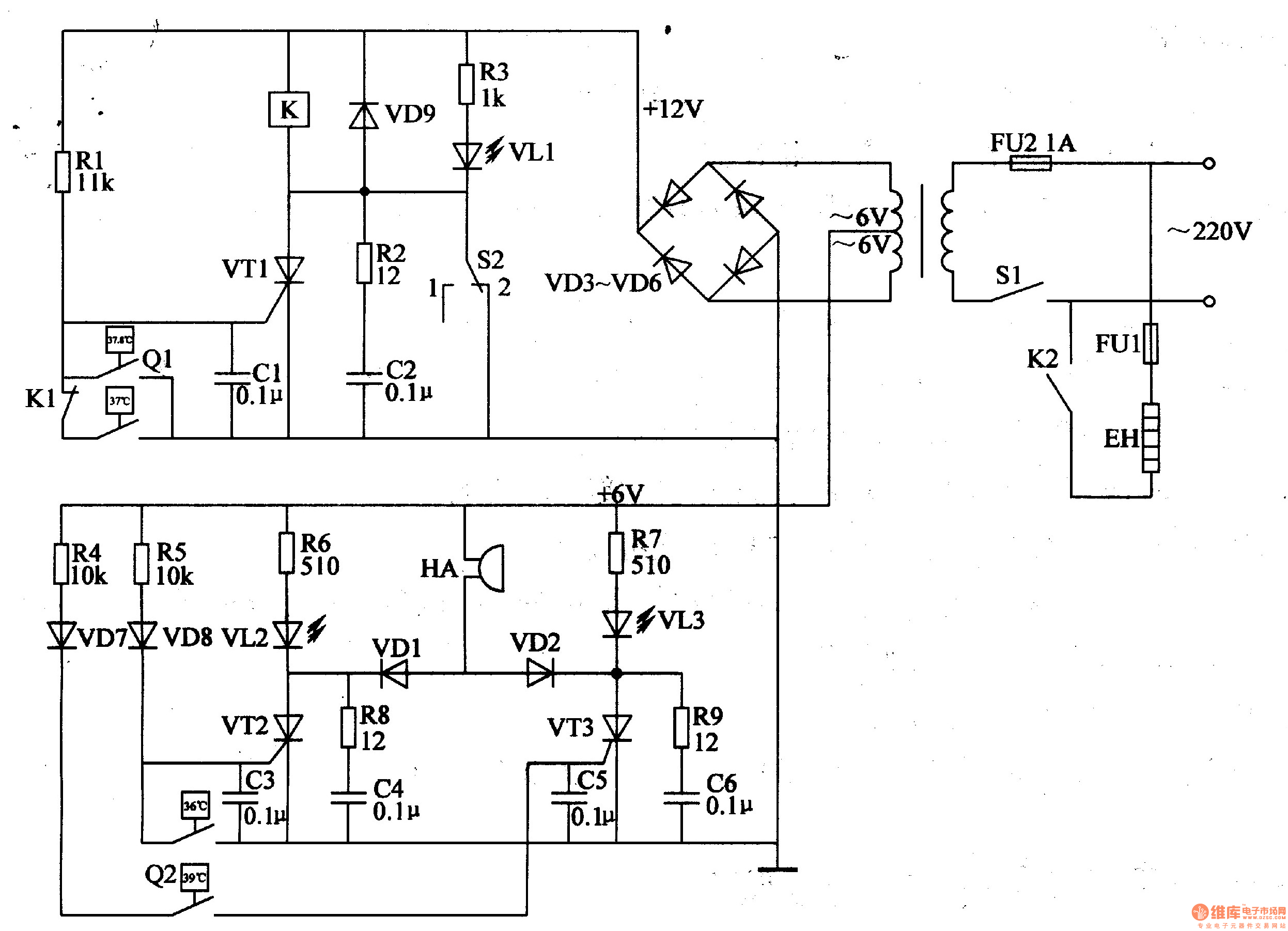
The egg hatching incubator circuit comprises a power supply circuit, a constant temperature control circuit, and a sound and light alarm circuit, as illustrated in Figure 4-7. The power supply circuit includes a power switch (S1), a fuse (FU2),...
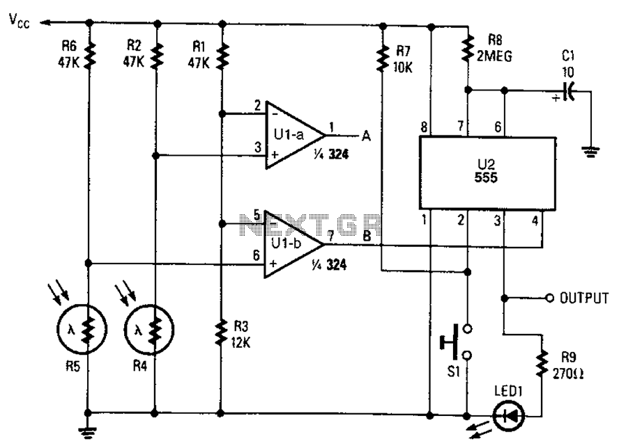
A combined monostable multivibrator using the 555 timer integrated circuit, along with a pair of light control comparators. This circuit can be utilized to control a load based on the timing parameters set within the circuit. The circuit comprises a...
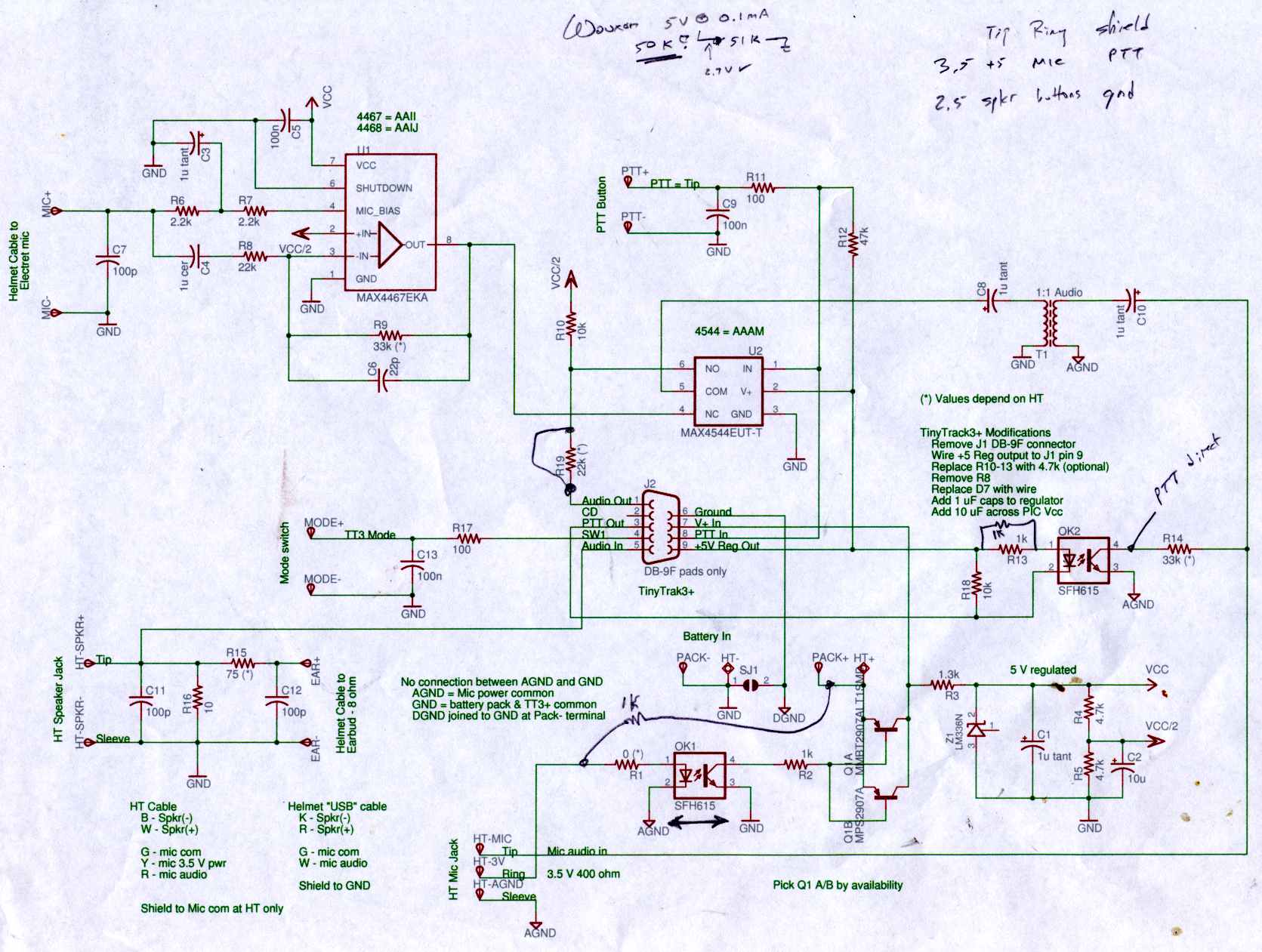
Connect the Byonics TinyTrak 3+ GPS modem, helmet earbud/mic, and external battery pack to the Z-1A, which is incompatible with the Wouxun. The KG-UV3D utilizes the Kenwood HT interface with a single ground for mic, speaker, and PTT functions,...