
Video-Out Coupling

To effectively implement a video distribution amplifier circuit, the design must include several key components to ensure optimal performance. The circuit begins with the LT1396 operational amplifier, selected for its high-speed capabilities and superior common-mode rejection ratio. The input stage of the circuit should be designed to accommodate a 75-ohm video signal, ensuring that the signal integrity is maintained throughout the transmission.
The incoming video signal is fed into the non-inverting input of the LT1396, while the feedback network is configured to set the gain to 2. This configuration involves placing a resistor in series with the output to achieve the desired output impedance of 75 ohms. The output stage should include multiple output taps, each following the same impedance matching principles to ensure that the signal remains consistent across all outputs.
To enhance the circuit's resilience against power supply failures, a high input impedance design is recommended. This allows the amplifier to tap into the video line without the need for its own termination resistor, thereby reducing the risk of signal loss during power outages. The use of RG1, a resistor optimized for common-mode rejection, aids in minimizing interference that could arise from ground loops or voltage differences between the cable shield and the circuit ground.
Trimmer potentiometers should be integrated into the design to allow for fine adjustments of the bandwidth, ensuring that the circuit can handle frequencies exceeding 10 MHz, which is essential for high-quality video transmission. This feature is particularly beneficial in applications where signal clarity and fidelity are paramount, such as in broadcast or professional video environments.
Overall, the implementation of this distribution amplifier circuit provides a reliable solution for distributing video signals to multiple destinations while maintaining signal integrity and minimizing interference. The LT1396's specifications and performance characteristics make it an ideal choice for such applications, and careful attention to circuit design will yield a robust and effective video distribution system.If you want to connect a video signal to several destinations, you need a distribution amplifier to match the 75-ohm video cable. A distribution amplifier terminates the incoming cable in 75 ohms and provides several outputs, each with 75-ohm output impedance.
Since this is usually achieved by putting a 75-ohm series resistor in the output lead of each video opamp (current-feedback amplifier), the opamps must be set up for a gain of 2 in order to achieve an insertion gain of 1 (0 dB). The disadvantage of this arrangement is that if the amplifier or its power supply fails, no signal is available at any of the outputs.
This can be remedied by using a high input impedance amplifier, which can be tapped into a video line without having to have its own 75-ohm termination resistor. In order to eliminate hum interference and voltage differences between the cable screen and the circuit earth, the circuit exploits the common-mode rejection of the opamp.
This can be optimized with resistor RG1. With the indicated LT1396 video opamp, more than 40 dB of common-mode rejection can be achieved. The signal bandwidth of the circuit can be optimized using the trimpots. It reaches to more than 10 MHz, which is quite acceptable for video signals. Thanks to the high-impedance connection to the video line, the video signal is not affected when the power for the coupled amplifier is switched off. You can learn more about the LT1396 from its data sheet at 🔗 External reference
Related Circuits
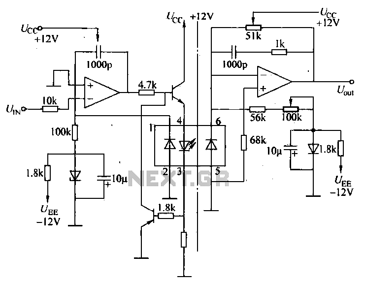
A universal optocoupler is utilized in electrocardiographs, as illustrated in Figure 5-29. Pin connections must be made carefully: the positive terminal should be connected to pin O, while the negative terminal should connect to the other pin. The control...
This circuit illustrates a 6-12 channel TV transmitter coupling circuit diagram. It is designed to stabilize the 10 P operation within the 6-12 channel range. The 6-12 channel TV transmitter coupling circuit is essential for ensuring stable transmission across multiple...
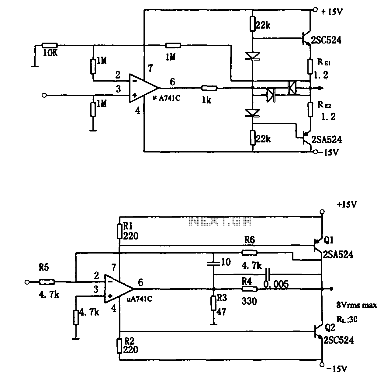
The direct coupling audio power amplifier utilizes an integrated operational amplifier. There are typically two practical configurations. The first configuration, depicted in (a), features a circuit structure that includes the output of the operational amplifier and a complementary symmetry...
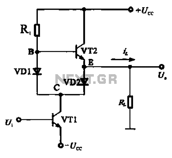
A Class AB output stage circuit is coupled with diodes, as illustrated in Figure 10-8. The static bias circuit for transistor VT1 (not shown) is adjusted so that the output at point E is at ground DC voltage UE....
This circuit is designed to drive a motor, and it has been suggested that a decoupling capacitor should be included to mitigate voltage spikes. There are conflicting opinions on the placement of this capacitor; some advise positioning it close...

Side tone coupling in telephones refers to the phenomenon where a person hears their own voice through the receiver while speaking. Excessive side tone can lead to a reduction in speaking volume and may cause feedback issues, while insufficient...