
Visible and Infrared Light Detectors

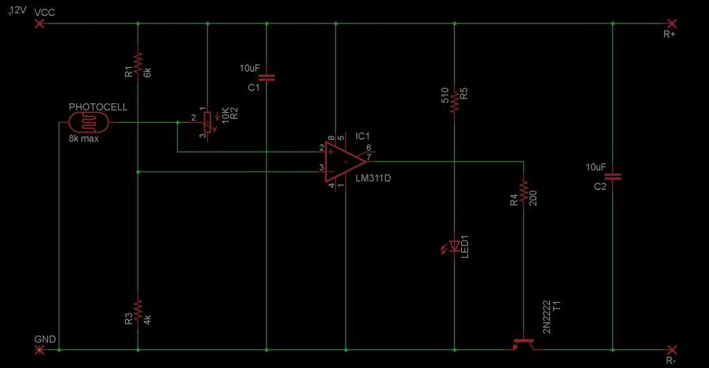
The circuit employs silicon phototransistors and CdS photocells as primary light-sensing components. Silicon phototransistors operate based on light intensity, where their conductance increases with the presence of light, allowing more current to flow. Conversely, in darkness, their conductance decreases, limiting the current. On the other hand, CdS photocells exhibit a change in resistance based on light exposure; they have low resistance in bright light and high resistance in darkness.
In the schematic, the phototransistors and photocells are connected to the input terminals of either the LM339 or LM393 voltage comparator integrated circuits. These comparators are essential for monitoring the voltage changes across the sensors. When the sensors detect varying light levels, the change in voltage is fed into the comparator, which compares this voltage against a reference voltage set by a voltage divider network.
The output of the LM339 or LM393 can be used to drive additional circuitry, such as relays, LEDs, or microcontrollers, depending on the application. The choice between using the LM339 (quad comparator) or LM393 (dual comparator) depends on the number of sensors and the complexity of the desired circuit. The design ensures that the system can effectively respond to changes in ambient light conditions, making it suitable for applications such as automatic lighting systems, alarm systems, or light-sensitive control systems.
For optimal performance, it is important to consider the specifications of the selected sensors and comparators, including their response times and operating voltage ranges, to ensure compatibility and reliability in the intended application.The sensors used are silicon phototransistors and Cadmium Sulfide (CdS) photocells. Both of these sensors allow less current to flow when they are dark than when lighted. Phototransistors change their conductance while photocells change their resistance depending on the intensity of the light falling on them. All of the detectors on this page use LM339 Quad or LM393 dual voltage comparator integrated circuits to detect the change in voltage across the sensor.
For information on Voltage Comparators please see the Voltage Comparator Information page at this site. 🔗 External reference
Related Circuits
The circuit below turns on a light corresponding to the first of several buttons pressed in a "Who's First" game. Three stages are shown but the circuit can be extended to include any number of buttons and lamps. Three...
The circuit is designed to sense ambient light levels and activate lights when it is dark. A prototype was successfully built on a breadboard using an LM324 comparator, various resistors, a trimmer resistor, and a photocell. Subsequently, a PCB...
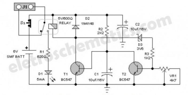
An emergency light is a light source designed to be available during emergencies. It operates automatically and is powered by a rechargeable battery. An emergency light system typically consists of several key components: a light source, a rechargeable battery, a...
This circuit features a white LED-based emergency light that provides several benefits. It is exceptionally bright due to the incorporation of white LEDs. The light activates automatically when the mains supply is interrupted and deactivates when mains power is...
IC4, C1, R1 and R2 are used for the clock pulse which is fed to both the counters IC2 and IC3 Pin 14. IC1 is a Flip Flop and is used as a switch to enable either IC2 or...
This automatic door light switch circuit activates a lamp when a door is opened and deactivates it when the door is closed again. The working principle of the circuit involves a sensor that detects the door's position. The automatic door...