
VISIBLE ELECTRIC CURRENT
The device presented here is an interactive real-time simulation of charge behavior within a wire. Instead of merely explaining concepts, it visually represents electric charges, allowing museum visitors to engage with them. The motion of its light patterns corresponds to the actual movement of charges in wires. When connected to a functional electrical circuit, it provides insight into the true nature of electricity. If individual conductors in a complex circuit are replaced with these devices, the operation of intricate electrical systems can be intuitively understood. "Visual Electricity" operates as an amp-meter with a "chaselight" circuit as the display mechanism. The Chaselight resembles a movie marquee light, with a sequence of lights that simulate motion. The input terminals of this device are located near the ends of a row of LEDs, with electric current measured between the terminals used to drive logic circuitry. The current does not directly power the LEDs; instead, logic circuitry lights every fourth LED, creating a visual representation of flowing "electrons." The direction and speed of the chaselight action reflect the direction and amperage of the current within the wire, giving observers a view of a wire filled with large, visible, movable electrons.
The input to the device consists of a standard current-meter circuit, featuring a low-value sampling resistor connected to an operational amplifier (op-amp). The voltage from this initial stage is adjusted in both amplitude and zero-level in the subsequent stage. The signal is then processed through a precision rectifier circuit, which outputs a full-wave signal along with a polarity signal. This polarity signal is level-shifted to control the forward/reverse direction of a shift register. The full-wave signal is fed into a Voltage-to-Frequency (V/F) converter, which drives the clock of the shift register. The outputs from the shift register are buffered and applied to four interleaved strings of LEDs.
When a small positive current is applied through the input terminals, the op-amps drive the V/F converter at a pulse frequency proportional to the current, causing the shift register to advance and the light pattern to move along the row of LEDs. Doubling the current results in a doubled frequency and a faster light pattern flow. Reversing the current direction changes the polarity signal, causing the shift register to decrement and the LED pattern to flow in the opposite direction. If a slow sine wave is applied, the LED pattern sways back and forth, mimicking the actual movement of charges within the wire. This device serves as a wire with visible electrons and functions as a current microscope, amplifying the speed of electron motion in wires. Contrary to common belief, electric current is a slow flow of charge, with electrons moving at speeds comparable to inches per hour. Even if individual electrons were visible, their motion would be imperceptible due to its slow nature. The Visual Electricity device depicts this motion several thousand times faster than it occurs in reality.
The circuit can be constructed affordably and simply using a single-chip microcomputer with an A/D input, such as the PIC16C7x. Presently, costs are high, but increased sales volume could facilitate a transition to surface-mount technology (SMT) packages and automated production, potentially lowering the price to below $10 each, allowing for distribution to individual students rather than a single device for a classroom. Future enhancements aim to eliminate the "jumping" of the LED pattern, as electrons in wires do not jump; they move smoothly, akin to water molecules, while also exhibiting thermal and quantum vibrations. Additionally, a "visible voltage" function could be integrated using red/green LEDs, measuring voltage at the input terminals relative to a third "ground" terminal. This would allow the display to indicate positive or negative voltages through color changes. The simultaneous display of voltage and current could be achieved, with the LED pattern reflecting changes in color and flow. For example, a square wave voltage would result in a red/green flashing display, while a sine wave would transition smoothly through red, yellow, and green.While working on an Electricity/Electronics exhibit for the Museum of Science in Boston I discovered a number of serious problems in attempting to explain simple electricity. One problem was the obscure way that exhibit devices typically present electrical effects: by using meters.
Sophisticated skills a re required to interpret meter readings and to imagine the invisible events they imply. Exhibit designers who are familiar with electronics sometimes fall into the trap believing that the general public also has their skills. And so designers include all sorts of digital and needle-meters as part of a display. But an electronics specialist sees a meter needle in quite a different way than does the unskilled public.
Meter readings usually serve more to obscure and complex-ify the exhibit than to reveal and enlighten. Think about it: if an exhibit makes you feel stupid, will you end up LIKING science No. The opposite occurs. A second problem: nearly all of the electricity explanations I found in children`s science textbooks were wrong, so I couldn`t use textbooks as a guide for explaining electricity at a simple level.
Go here for more about this. And third, as an electrical engineer I had a gut-level feel for the math behind electronics, yet my entire non-math picture of electricity was mostly based on the incorrect explanations found in K-6 textbooks. As a designer, I`d been living in a world of electronics math, never realizing that my verbal and visual explanations for electrical phenomena were totally incompatible with the mathematical description.
My verbal and visual explanations were WRONG. But as long as I stuck with engineering, used design equations and CAD software, I was fine, but if I tried to use any non-math concepts to tell others what I knew, I would be spreading misinformation. Visible Electricity The device depicted here was my best shot at a solution. It`s an interactive realtime simulation of the behavior of charges within a wire. Rather than explaining anything, instead it just makes electric charges visible so museum visitors can play with them.
The motion of its pattern of lights follows the actual motion of charges in the wires, and when the device is connected into a real functional electrical circuit, it provides a window on the true nature of "electricity. " If all the individual conductors in a complex circuit are replaced by a number of these devices, the operation of a complicated electrical device can be directly observed and intuitively understood.
"Visual Electricity" is simply an amp-meter having a "chaselight" circuit as a readout device. A Chaselight is identical to a movie marquee lightbulb border, with a pattern of on and off lights which advance along and simulate motion. The input terminals of my device are physically placed near the ends of a row of LEDs, and electric current passing between the terminals is measured and used to drive some logic circuitry.
The current being measured does not drive the LEDs directly of course. The logic circuitry lights every fourth LED, and by advancing this pattern of LEDs, a row of glowing "electrons" can be made to flow along. The direction and speed of chaselight action is proportional to the direction and amperage of electric current inside the wire.
To the observer this device behaves as a wire which contains large, visible, movable electrons. SCHEMATIC The input to the device is a standard current-meter circuit: a low-value sampling resistor connected to an opamp. The voltage from this first stage is adjusted in amplitude and zero-level by the next stage. The signal is then applied to a precision rectifier circuit which outputs a fullwave signal and a polarity signal.
The polarity signal is level-shifted and is used to control the fwd/rev direction of a shift register. The fullwave signal is applied to a Voltage-to-Frequency (V/F) converter whose output is used to drive the clock of the shift register.
The four outputs of the shift register are buffered and applied to four interleaved strings of LEDs. OPERATION When a small positive current is applied via the input terminals, the opamps drive the V/F converter at a pulse frequency proportional to the amperage, the shift register begins advancing, and the pattern of lights starts moving slowly along the row of LEDs. If the current is doubled, the frequency doubles and the pattern "flows" twice as fast. If the direction of current is reversed, the polarity signal changes state, the shift register starts decrementing, and the LED pattern flows in the opposite direction.
If a very slow (1 Hz) sine wave is applied to the input, the LED pattern will swerve back and forth, just like the charges actually do within the wire. The above device is a wire with visible electrons. It also is an electric current microscope, since it greatly amplifies the speed of electron motion which occurs in wires.
Contrary to popular belief, electric current is a very slow flow of electric charge. At normal densities of electric current, electrons move at speeds on the order of inches per hour, like the minute hand on a clock. Even if individual electrons could be seen by human eyes, their flowing motion would be invisible because it`s just too slow.
Visual Electricity depicts this motion several thousand times faster than it actually is. The whole circuit could be made cheap and simple through use of a single chip microcomputer having a A/D input, such as PIC16C7x. Right now the price is very high. If the sales volume went up, I could change over to SMT packages and automatic production; maybe get the production price down below $10 each, so each student could have one, as opposed to a single expensive device for one classroom as things stand now.
The next advancement is to make the LED pattern stop jumping. Electrons in wires don`t jump (they behave more like water molecules; moving along smoothly but also jittering around with thermal/quantum vibrations. ) Also, one common misconception involves the (wrong) idea that electrons jump from atom to atom. So I need to get rid of the jumping. Add a PWM cross-fader algorithm, so the light pattern moves smoothly from LED to LED without jumping.
A further advancement is to add a "visible voltage" function. This could be done through use of red/green LEDs, by measuring the voltage on the input terminals with respect to a third "ground" terminal connected to conductive rubber legs, then driving the R/G LEDs with a pulse-width modulated signal. If Visual Electricity as a "wire" is then connected to a positive voltage source, the display turns red.
If negative, it turns green. If disconnected, it could either maintain an "electrostatic charge" like a real wire and remain at its last color, or it could turn yellow (50-50 red/green). The voltage and current on a single wire could then be displayed simultaneously with "electrons" which change color, flow along, or both.
A square wave voltage signal would be a red/green flashing. A sine wave signal would change smoothly: red/yellow/green and back again. - Bill Beaty, 6/28/95 Brief history: 1987 Brainstorm! While on a trip to Exploratorium in California, I realize that their displays with current meters could be replaced with schematics with "chaselight" LEDs, with current probes to move the LEDs proportional to the actual current in the wires. 1988 I design an etch PCBs as "chaselight" current meters, and build a temporary exhibit: a motor-generator pair with green LED chaselights to indicate the electron flow as one or the other crank is turned.
I want to build a microprocessor version but don`t know assembler for the MC68705. I also want to build a version with red/green LEDs controlled by conductor voltage (with some sort of reference, perhaps use metal magnets on the bottom and stick them to a metal board mounted on the wall. ) 1989 Chaselight meters are built into two exhibits in the VandeGraaff Hall (this just after I moved to Seattle.
) 1990 In Dinamation Inc. , I demonstrate the device to the company pres. I imagine building a hall-effect current sensor or clamp-on probe, so the LEDs will flow in the correct direction regardless of which way the row is oriented. 1992 I etch a long thin two-PCB version using bar-graph LED modules and rechargable batteries. TEKNOS Inc. sells a set of ten "chaselight current meters" to LLNL (or was it LANL ), delivered Jan/93. 1993 Arbor Scientific produces a less expensive version in a plastic tube using discrete LEDs and 9V battery, advertised in their `94 catalog.
1994 I learn assembler for MC68705 and microchip PIC, but *still* haven`t got off my butt to build a one-chip version or a red/green version. 1995 I start a webpage; upload my schematics and PCBs so anyone can build the device. 1996 Arbor Scientific starts a website store, so finally teachers on internet can buy my invention. 2004 I talk with D. Durlach, who uses the electric current chaselight idea in an exhibit for New York Hall of Science. 2005 Completely independantly, Kamata and Hara of Tokyo Gakugei University invent a much improved color-changing version with voltage/current sensing, based on a PIC microprocessor.
See: 🔗 External reference
Related Circuits
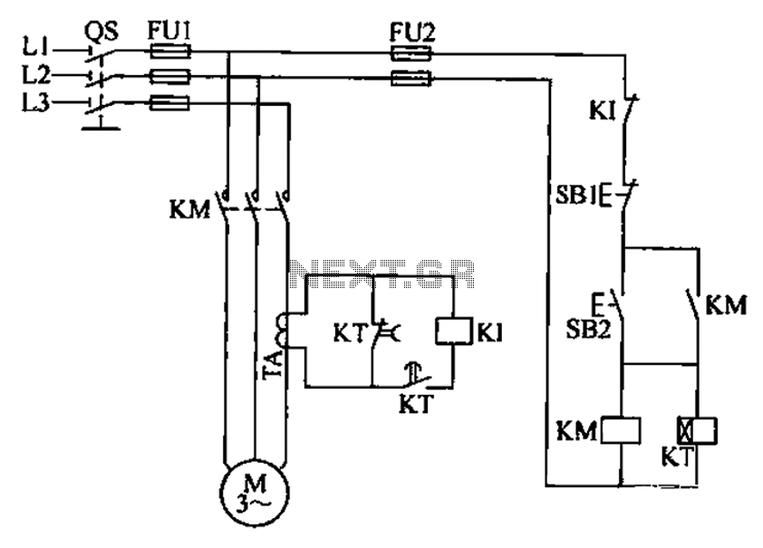
A three-phase electric motor overcurrent protection circuit. This example circuit utilizes a transformer to monitor the current, ensuring that the currents in the three-phase motor do not exceed normal operating levels. When the current exceeds the set threshold, the...
In this circuit, an LM339 quad voltage comparator is utilized to generate a time delay and control a high current output at low voltage. Approximately 5 amps of current can be sourced using a pair of fresh alkaline D...
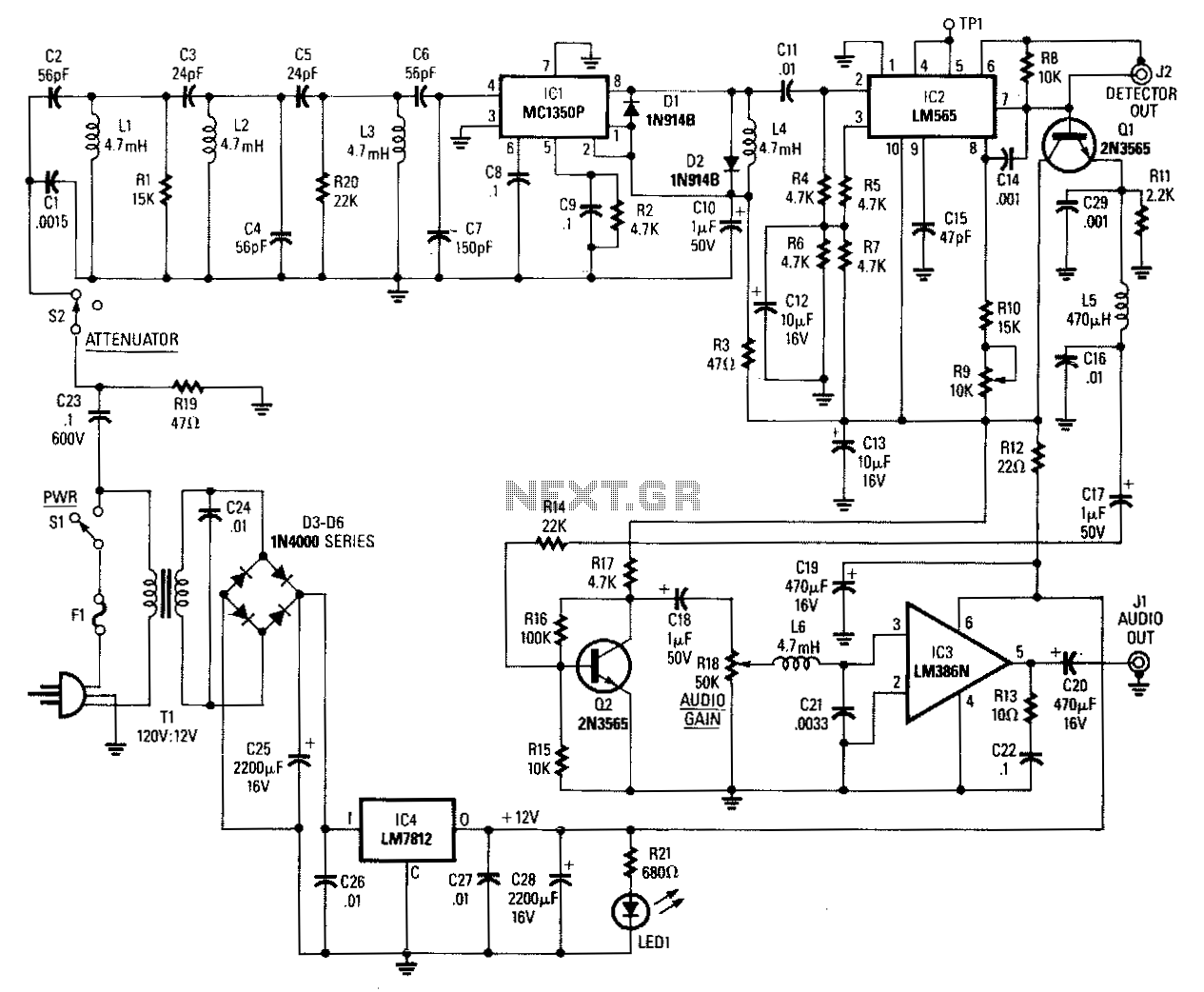
Input signals from the power line are coupled through C23 and R19 to the input filter network. C23 must be rated at 600 volts. Switch 52 is used as an attenuator. Components C2 through C7, L1 through L3, R1,...
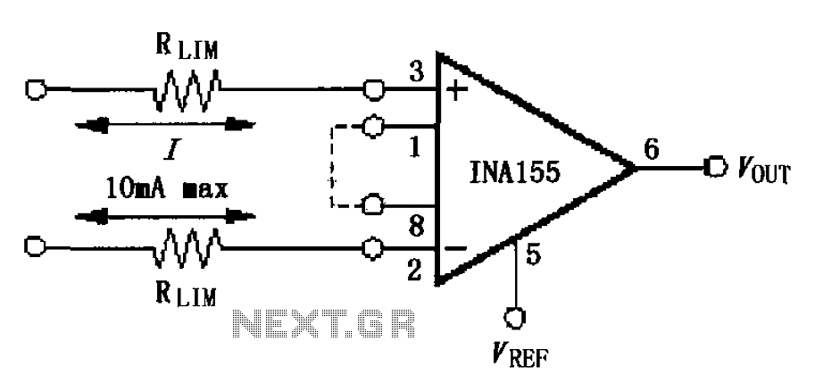
The input current protection circuit is illustrated in FIG, utilizing INA155/156. The INA155 features internal electrostatic discharge (ESD) protection diodes that become active when the input voltage exceeds the supply voltage by 500mV. In this scenario, the protection diodes...
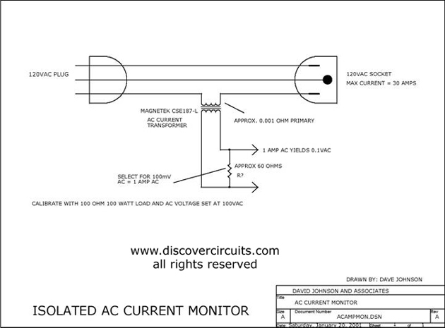
This circuit utilizes a small AC current transformer from Magnetek to generate an isolated voltage that is proportional to the AC current flowing through the primary winding. The AC current transformer operates on the principle of electromagnetic induction, where the...
A current regulator functions as a load when connected to a voltage source or in series between a voltage source and an actual load. The primary characteristic of a current regulator is to maintain a constant current output regardless...
Warning: include(partials/cookie-banner.php): Failed to open stream: Permission denied in /var/www/html/nextgr/view-circuit.php on line 713
Warning: include(): Failed opening 'partials/cookie-banner.php' for inclusion (include_path='.:/usr/share/php') in /var/www/html/nextgr/view-circuit.php on line 713