
ISOLATED AC CURRENT MONITOR

The AC current transformer operates on the principle of electromagnetic induction, where the primary winding, through which the AC current flows, creates a magnetic field. This magnetic field induces a proportional voltage in the secondary winding of the transformer. The isolation provided by the transformer is crucial for safety and performance, as it separates the measurement circuit from the high-voltage AC line.
In a typical application, the primary winding is connected in series with the load whose current is to be measured. The secondary winding, which produces the isolated voltage output, is connected to a measurement device, such as an analog voltmeter, a microcontroller's analog input, or a signal conditioning circuit.
The output voltage from the transformer is typically a low-level AC signal that may require further processing. This can involve rectification to convert the AC signal to a DC signal, followed by filtering to smooth out the output and amplifying to a usable level.
It is essential to select the appropriate turns ratio of the transformer to ensure that the output voltage is within the desired range for the measurement system. Additionally, the frequency response of the transformer should be considered, as it affects the accuracy of current measurement across different frequencies.
Overall, this circuit configuration is widely used in various applications including power monitoring, energy management systems, and protective relaying in electrical installations. Proper design and implementation of this circuit ensure accurate measurement of AC currents while maintaining electrical isolation and safety.This circuit uses a small AC current transformer from Magnetek to produce an isolated voltage proportional to the AC current in the primary winding 🔗 External reference
Related Circuits
This circuit is a two-wire light level detector, which does not separate the wires for power supply and output signal delivery. It operates using a current loop that performs both functions over a single pair of cables, requiring only...
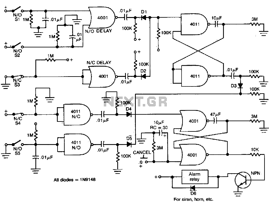
This circuit provides normally open (NO) and normally closed (NC) contacts SI, S2, and S3 to activate the alarm after a 30-second delay. S4 and S5 operate instantly. The CANCEL switch resets the alarm. The described circuit functions as a...
The UTC H1277 is a semiconductor integrated Hall Effect Sensor integrated circuit (IC). It is designed for applications where the accurate tracking of small magnetic flux density changes is critical. The H1277 can be utilized in various applications, including...
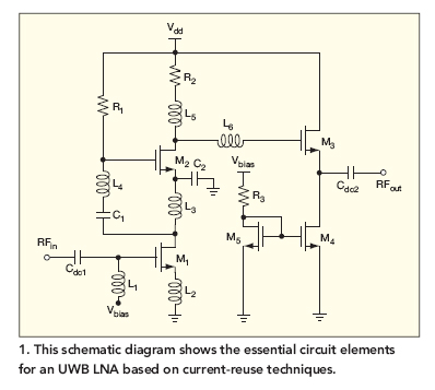
This broadband low-noise CMOS amplifier operates within the ultrawideband (UWB) communications frequency range of 3.1 to 10.6 GHz, utilizing current-reuse techniques. The broadband low-noise CMOS amplifier is designed to enhance signal integrity and minimize noise within the specified UWB frequency...
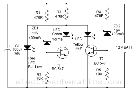
This is a simple battery monitor circuit designed for a quick assessment of a 12-volt lead-acid battery. Continuous monitoring of battery charge is essential to extend its lifespan. The battery monitor circuit typically consists of a voltage divider, an operational...
As depicted in the image, when the output current surpasses 40mA, the internal resistance of 50Ω in the XTR110 (R9) must be substituted with an external resistance, REXT. This external resistance is connected between pins 13 and 16. The...