
Vocal Stripper Circuit

The circuit described involves a sophisticated audio processing system designed to manage the distribution and manipulation of audio signals across multiple frequency bands. The use of buffer amplifiers C4-a and C4-b ensures that the integrity of the right- and left-channel signals is maintained before they are fed into the active crossover IG5. This crossover plays a critical role in separating the audio signals into distinct frequency ranges, facilitating more effective processing of low, mid, and high frequencies.
The low-frequency signals are directed to the mixer IC6-c, which allows for the blending of these signals with other audio components. Meanwhile, the middle and high frequencies are routed to analog delay lines 1C1 and 1C2. These delay lines introduce specific time delays to the audio signals, which can enhance spatial effects and improve the overall sound quality by allowing for phase adjustments between channels.
After passing through the delay lines, the output signals are processed by IC6-a and IC6-d, which serve to filter out unwanted high-frequency artifacts, ensuring that only the desired frequencies are sent forward in the signal path. The remixed signals from 106-b are then combined with the low-frequency output by 106-c, ultimately reaching the final output stage through buffers IC4-c and IC4-d. This buffering stage is crucial for driving the output load effectively while maintaining signal fidelity.
The right channel's variable-delay circuit, which employs an analog bucket-brigade device, introduces a unique capability for dynamic sound manipulation. By varying the clock frequency, the delay can be adjusted, providing a rich and versatile audio experience. This variable delay is compared in amplitude and phase to the left channel, which maintains a fixed delay, allowing for precise control over the stereo imaging of the audio signal.
Additionally, the presence of resistor R36 allows for the nulling out of local interference or unwanted signals, enhancing the clarity and quality of the audio output. This feature is particularly useful in fine-tuning the performance of the circuit, ensuring that the final audio experience is as clean and engaging as possible. Right- and left-channel signals pass through 1 C4-a and -b buffer amps into active crossover IG5; low frequencies are sent to the IC6-c mixer, and middle and high frequencies are sent to the analog delay lines of 1C1 and 1C2. That output passes through lC6-a and -d to filter high- frequency sample steps. 106-b signals are remixed with low frequencies by 106-c and are sent to final out via IC4-c, and -d buffers.
One channel (R) is a variable-delay circuit, using an analog bucket-brigade device and a variable clock frequency. This is compared in amplitude and phase to the L channel (fixed delay). The local can therefore be nulled out via R36.
Related Circuits
The following circuit diagram depicts a 100 Watt audio power amplifier, constructed using the LM3886 power amplifier chip. A single LM3886 IC can amplify audio power output up to 68W. In this circuit, two LM3886 chips are configured in...

This is the design circuit diagram of an ultrasonic mosquito repeller. The circuit operates based on the theory that insects, such as mosquitoes, can be repelled by sound frequencies in the ultrasonic range (above 20 kHz). The circuit utilizes...
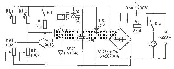
This is a remote-controlled light switch circuit that can be used for remote control toys, flashlight operation, or laser pointers. When the light from a torch illuminates the photosensitive resistor RL2, its resistance decreases, causing transistor VT2 to turn...
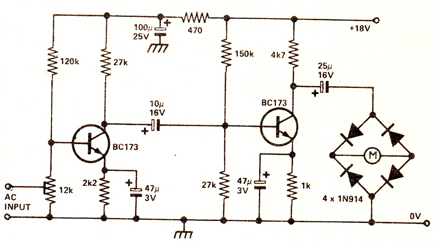
The circuit illustrates a two-stage voltage amplifier that drives a recording level meter. An AC signal input is amplified and rectified, with the resulting DC voltage displayed on the meter. This circuit is compatible with tape recorders or audio...
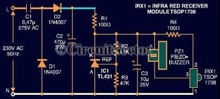
This document presents an infrared remote control tester circuit that can be constructed at a low cost. The circuit is built around the infrared receiver module TSOP1738. The state of the remote control can be observed through the sound...
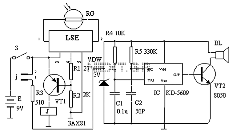
The circuit principle is illustrated in the accompanying figure. When the night light shines on the photosensitive resistor RG, it exhibits a high resistance (significantly greater than 50K). As a result, the output of the LSE pin is low,...