
Voice Disguiser Circuit

At this stage, the voice frequency spectrum is inverted (e.g., lower frequencies become higher, and vice versa), rendering the voice signal entirely unintelligible. The output from the first low-pass filter is sent to a second modulator, composed of U1-c, U1-d, and U3-b, where it undergoes frequency modulation using the output from the second carrier oscillator, made up of U3-c and U3-d; the frequency of this second oscillator is adjusted by potentiometer R36. The output of the second modulator is filtered by a second low-pass filter, consisting of U2-d and several supporting components, and is subsequently amplified by Q3. The voice output signal from Q3 is then transmitted to U4 (an LM386 low-voltage audio power amplifier) through an impedance-matching transformer, T1. The output from U4 is used to drive SPKR1 (an 8-ohm speaker). During operation, if both carrier oscillators are set to the same frequency, the voice signal from the speaker replicates the input signal from the microphone. However, varying the frequency of the second oscillator (via R36) alters the output voice signal's frequency, causing the reproduced voice to sound either higher or lower in pitch than normal.
The voice disguiser circuit is designed to obscure the original voice signal effectively. The use of a microphone (MIC1) initiates the process by capturing the audio input, which is then amplified to ensure sufficient signal strength for further processing. The low-pass filter integrated within the amplifier circuit limits the frequency range to eliminate any high-frequency noise that may interfere with the modulation process.
The balanced modulator configuration is crucial for creating the double-sideband suppressed-carrier signal, which is essential for the subsequent frequency inversion. By utilizing two oscillators, the circuit allows for the manipulation of the output signal's frequency, providing flexibility in voice modulation. The second modulator further enhances the disguise effect by applying frequency modulation to the already inverted signal.
The final amplification stage, using the LM386, is tailored for low-voltage applications, making it suitable for battery-powered or portable devices. The impedance-matching transformer ensures proper coupling between the amplifier and the speaker, optimizing the sound output. The design allows for real-time adjustments of the modulation frequency, enabling users to customize the pitch of the voice output, thereby enhancing the versatility of the voice disguiser. A complete schematic diagram of the voice disguiser is shown. Microphone MIC1 picks up the voice signal and feeds it to an audio amplifier, consisting of Ql and Q2, and a few support components. The amplifier has a low-pass gain response that limits the voice frequencies to 5 kHz or lower. The voice signal is then fed to the input of the first, balanced modulator, which is comprised of Ul-a, Ul-b, U2-a, and U3-a.
The output of the first 4-kHz oscillator, built around U3-f and U3-e, is fed to the carrier input of the first, modulator. The frequency of the first oscillator is controlled by the setting of potentiometer R13. The modulator outputa double-sideband suppressed-carrier signal centered on 4 kHzis then filtered by the first 5-kHz low-pass filter, formed by U2-b, which eliminates the upper-sideband signals.
At this point, the voice frequency spectrum is inverted (e.g., the frequencies that were low now become high, and vice versa), making the voice signal completely unintelligible. The output of the first low-pass filter is fed to a second modulator formed by Ul-c, Ul-d, and U3-b, where it is frequency modulated with the output of the second carrier oscillator, comprised of U3-c and U3-d; the frequency of the second oscillator is controlled by potentiometer R36.
The output of the second modulator is filtered by the second low-pass filter, which consists of U2-d and few support components, and amplified by Q3. The voice output signal from Q3 is fed to U4 (an LM386 low-voltage, audio-power amplifier) through an impedance-matching transformer, Tl.
The output of U4 is then used to drive SPKR1 (ari 8- speaker). In operation, if both carrier oscillators are set to the same frequency, the voice signal from the speaker will be an exact duplicate of the input signal from the microphone. However, if the frequency of the second oscillator is varied (via R36), the output voice signal also shifts in frequency.
That makes the voice reproduced by the speaker sound higher- or lower-pitched than normal.
Related Circuits
Colour sensor is an interesting project for hobbyists. The circuit can sense eight colours, i.e. blue, green and red (primary colours); magenta, yellow and cyan (secondary colours); and black and white. The circuit is based on the fundamentals of...
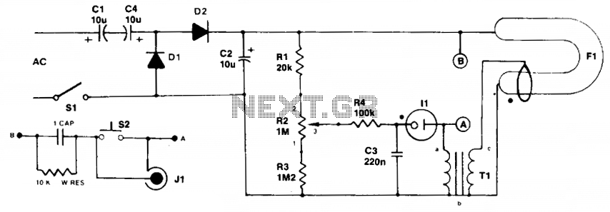
Initially, the neon and xenon lamps do not conduct and behave like very high (almost infinite) resistance. Capacitors C1 and C4, in conjunction with diodes D1 and D2, form a voltage doubler circuit, allowing C2 to charge up to...
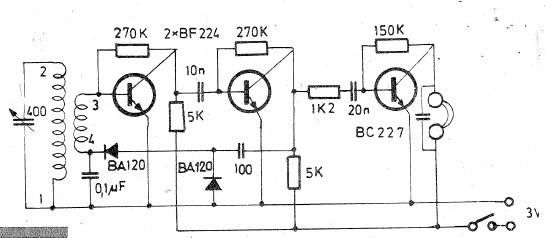
Oscillating circuits (coils) are constructed on a ferrite bar. For long wave reception, winding "1-2" consists of 135 turns, while winding "3-4" has 20 turns. For medium wave reception, winding "1-2" has 75 turns, and winding "3-4" has 7...
This circuit below shows a teleremote circuit that enables the switching on and off of appliances through telephone lines. The teleremote circuit utilizes a telephone line as a medium for controlling electrical appliances from a distance. The primary components...

Capacitor start single-phase induction motor circuit configuration, in order to form a two-phase rotating magnetic field, starting winding and capacitor in series, the same magnetic field can be formed automatically. The capacitor start single-phase induction motor utilizes a specific circuit...
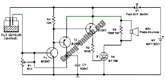
This design features a simple circuit for a tilt sensor alarm that can be constructed using readily available and inexpensive components. The circuit is based entirely on transistor technology. The homemade tilt sensor for this circuit utilizes a standard...