
Voltage Controlled Gain Video Amplifier

The concept of voltage-controlled gain adjustment is integral to many electronic circuits, particularly in audio processing and instrumentation applications. A voltage-controlled amplifier (VCA) can be employed, where the gain of the amplifier is adjusted based on an input voltage signal. This configuration enables users to manipulate gain settings dynamically, enhancing the adaptability of the system.
In a typical implementation, the input voltage signal may originate from a potentiometer, a digital-to-analog converter (DAC), or an external control voltage source. The VCA can be designed using operational amplifiers (op-amps) configured in a feedback loop, where the gain is determined by the resistance values in the feedback path. By varying the control voltage, the resistance can be adjusted, thus modifying the gain of the amplifier.
For instance, consider a circuit where an op-amp is used in a non-inverting configuration. The gain (Av) can be expressed as Av = 1 + (R2/R1), where R1 is the resistor connected from the inverting input to ground and R2 is the feedback resistor. By replacing R2 with a variable resistor controlled by a voltage signal, the gain can be continuously adjusted. This method allows for precise control over the amplification process, making it suitable for applications requiring fine-tuning of audio levels or signal processing.
In addition, incorporating a microcontroller can offer further enhancements, such as programmable gain settings, automatic gain control (AGC), or user-defined presets. The microcontroller can read input from user interfaces like knobs, sliders, or touchscreens, converting these inputs into corresponding voltage signals to adjust the gain dynamically.
Overall, the flexibility of utilizing a voltage signal for gain adjustment significantly enhances the functionality and user experience of electronic systems, facilitating a wide range of applications in modern electronics.Gain adjustment will be more flexible if it controlled by a voltage signal, since we can use many methods to provide user interface. We can control it by a.. 🔗 External reference
Related Circuits
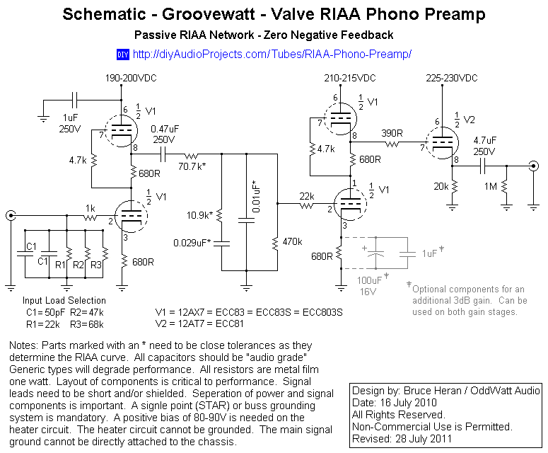
This project has been in development for over a year, initially postponed due to concerns about design complexity and the availability of high-quality phono preamps. The objective was to create a preamp that would deliver performance comparable to commercial...
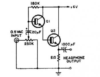
This schematic diagram illustrates a simple headphone amplifier circuit constructed using two NPN transistors. Suitable transistor options include the BC549C, as well as other NPN transistors such as the European equivalents BC548C, BC547C, BC239, 2N5818, or 2N2222. An audio...
It is important to note that there is limited protection circuitry and fuses in this amplifier. A short turn-on delay for the output power supply is included to minimize thumps, along with a couple of line fuses, but no...

This amplifier was designed to be self-contained in a small loudspeaker box. It can be fed by Walkman, Mini-Disc, iPod, CD players, computers, and similar devices fitted with line or headphone output. Of course, in most cases, you will...
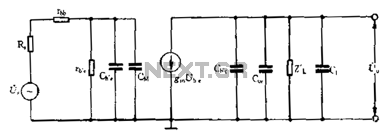
Common emitter amplifier circuit with resistance and capacitance coupling. The common emitter amplifier circuit is a fundamental configuration in analog electronics, widely utilized for its ability to amplify voltage signals. This circuit employs a bipolar junction transistor (BJT) as the...
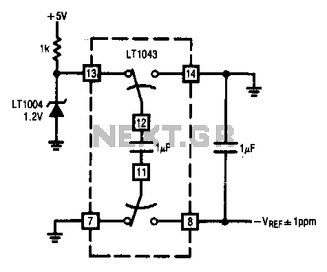
This circuit enables the inversion of a reference signal with an accuracy of 1 ppm. It features high input impedance and does not require any trimming. The described circuit is designed to invert a reference voltage signal while maintaining a...