
555 Low Voltage Operation

The 555 timer IC is a versatile device commonly used in various timing, delay, pulse generation, and oscillator applications. Its performance can indeed be affected by the supply voltage, particularly when operating below the nominal 5V. At lower voltages, the internal thresholds for triggering and resetting may not function optimally, leading to unreliable operation.
To enhance the performance of the 555 timer at lower voltages, several strategies can be employed. One approach is to utilize a low-voltage variant of the 555 timer, such as the LMC555 or TLC555, which are specifically designed to operate efficiently at supply voltages down to 2V. These alternatives provide improved performance characteristics and maintain stable operation across a wider voltage range.
Another method involves careful selection of external components, such as resistors and capacitors, to optimize the timing intervals and ensure the circuit functions correctly even at lower voltages. For instance, using precision resistors can help maintain consistent charge and discharge times for the timing capacitor, which is crucial for achieving accurate timing intervals.
Additionally, implementing a voltage regulator or a boost converter can help maintain a stable supply voltage above the critical threshold, ensuring that the 555 timer operates within its optimal range. This can be particularly useful in battery-powered applications where the supply voltage may drop as the battery discharges.
Overall, understanding the limitations of the 555 timer at lower Vcc levels and applying these strategies can lead to improved reliability and functionality in various electronic applications.I had heard some stories in the past concerning how poorly the 555 ran below Vcc = 5V, so I embarked on an endeavor to see if I could improve operation. Th.. 🔗 External reference
Related Circuits
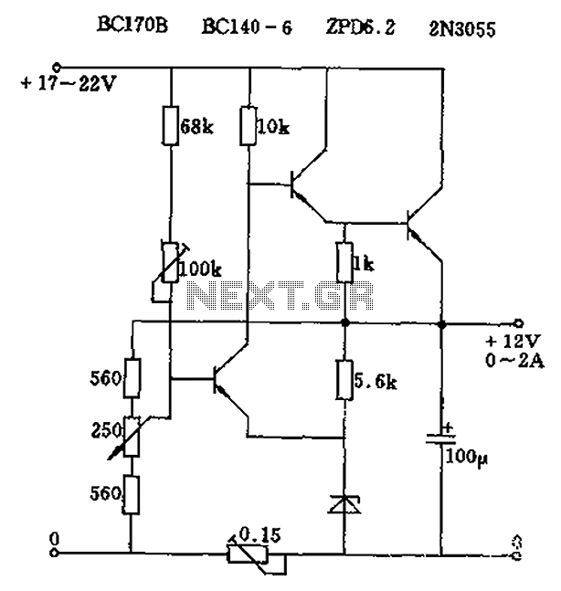
The circuit output voltage can be continuously adjusted from zero to its maximum value. The baseline is established by a constant current sourced from the auxiliary power supply circuit. The reference current of 500 microamperes can be fine-tuned to...
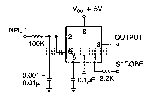
This timer serves as an effective line receiver for control applications that involve relatively slow electromechanical devices. It operates without the need for special drivers over single, unshielded lines. The timer circuit is designed to facilitate communication between control systems...
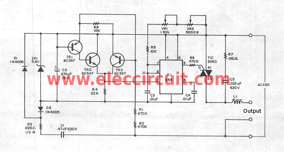
The super dimmer is an improved version compared to the standard dimmer currently in use. Testing its performance will provide a clearer understanding of its advantages. The super dimmer operates using advanced technology that allows for finer control over...

The circuit of the transmitter is depicted in Figure 1, showcasing its simplicity. The initial stage is the oscillator, which is tuned using a variable capacitor. To select an unused frequency, adjust C3 carefully until background noise ceases (the...
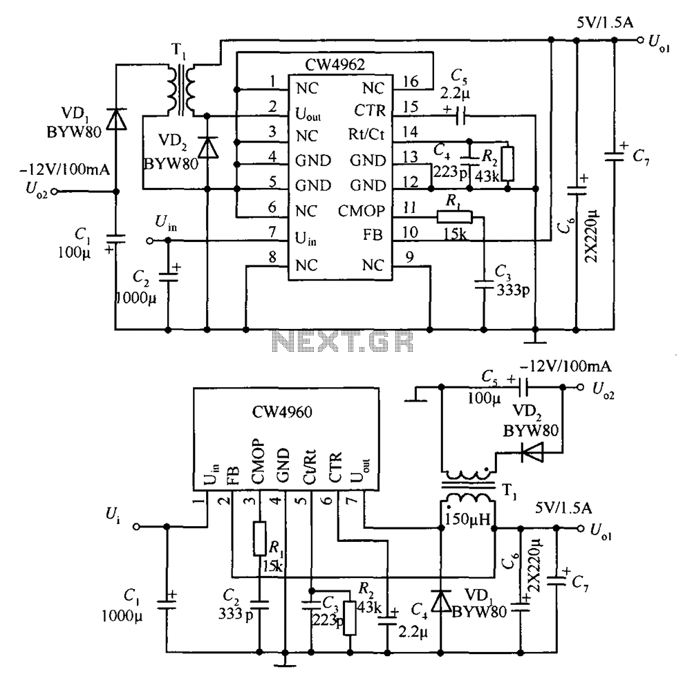
The circuit described is a stabilized power supply utilizing the CW4962 and CW4960 components, providing +5V at 1.5A and -12V at 100mA. The +5V output serves as the main power supply. The output circuit employs a transformer rather than...
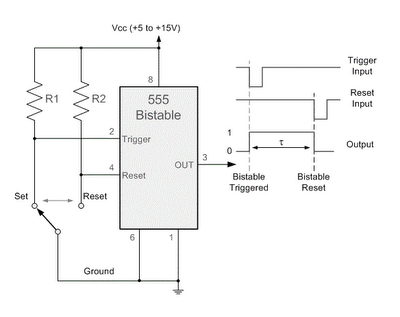
By applying a "LOW" signal to the Trigger input (pin 2) while the switch is in the Set position, the output state changes to "HIGH". Conversely, applying a "LOW" signal to the Reset input (pin 4) while the switch...