
Voltage Regulator Calculation

Adjustable voltage regulators, such as the LM317 and LM337, are widely used in electronic circuits to provide a stable output voltage that can be adjusted based on the needs of the application. The design process begins with the calculation of resistors R1 and R2, which set the output voltage according to the formula provided. The reference voltage (VREF) is typically 1.25 V for the LM317 and 1.2 V for the LM337, which is crucial for determining the output voltage.
To ensure optimal performance, it is essential to select resistor values that not only meet the voltage requirements but also allow for adequate current flow through the circuit. In many cases, using a standard resistor value for R1, such as 120 Ω, simplifies the design process while ensuring that the voltage regulator operates efficiently.
When calculating R2, it is important to remember the relationship between the output voltage and the reference voltage. The voltage drop across R2 must be sufficient to provide the desired output voltage, and the calculated resistance should be readily available as standard resistor values to facilitate assembly.
For example, when targeting an output voltage of 5 V, the calculation will yield R2 = 3.8 kΩ. In practical scenarios, this can be achieved by combining standard resistor values, such as a 3.3 kΩ resistor in series with a 470 Ω resistor, to reach the desired total resistance.
In conclusion, designing an adjustable voltage regulator circuit involves careful consideration of resistor values to achieve the desired output voltage while ensuring sufficient current flow. By following the outlined method and using standard resistor values, the design process can be streamlined, leading to efficient and reliable voltage regulation in various electronic applications.Before you can design an adjustable voltage regulator into your circuit, or do a redesign, you need to calculate the values for two resistors. This is not difficult in itself, but actually finding the right resistors may pose problems. Fortunately a trick is available to make it all much easier. With most adjustable voltage regulators like the LM3 17 and LM337, the input voltage has to be 1. 2 to 1. 25 volts above the desired output voltage. This is because the voltage at the ADJ (adjust) input is internally compared to a reference voltage with that value. The reference voltage always exists across R1. Together with preset R2 it determines the current flowing through the ADJ pin, as follows: Vout = VREF [1+(R2/R1)]+I ADJ R2 If for the sake of convenience we ignore I ADJ, enter the reference voltage (1.
2 V) and for R1 select a value of one thousand times that voltage (i. e. , 1. 2 k ) then the equation is simplified to: R2 = 1000 (Vout 1. 2) In practice, simply determine the voltage drop across R2 (output voltage minus reference voltage) and you get your resistance value directly in kilo-ohms. For example, for 5 V R2 becomes 5 1. 2 = 3. 8 k which is easiest made by connecting 3. 3k and 470R resistors in series. In the case of relatively low voltages, smaller resistor values are recommended. This is because sufficient current needs to flow to enable the voltage regulator to do its job. A simple solution is to choose, say, 120 for R1. R2 then becomes: R2 = 100 (Vout 1. 2) Be the first of your friends to get free diy electronics projects, circuits diagrams, hacks, mods, gadgets & gizmo automatically each time we publish.
Your email address & privacy are safe with us ! 🔗 External reference
Related Circuits
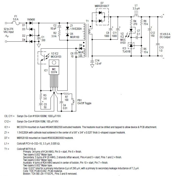
This switching power supply circuit diagram is based on the MC33374 high-power voltage switching regulator IC manufactured by Motorola Semiconductor. The MC33374 switching power supply circuit will provide a maximum output power of around 90 W and requires few...
This is a basic flash memory programming voltage supply circuit. This circuit utilizes the LT1072 switching regulator to generate high voltage by driving the inductor L1 and resistor R2. The basic flash memory programming voltage supply circuit is designed to...
This is a CMOS IC (CD4033) based circuit which can be used to detect presence of mains AC voltage without any electrical contact with the conductor carrying AC current/voltage. Thus it can be used to detect mains AC voltage...
10V high-stability voltage source model power supply. Refer to the specified page for an explanation regarding the associated circuit diagram. The 10V high-stability voltage source is designed to provide a reliable and consistent output voltage, making it suitable for various electronic...
The design is based on the TubeHobby and serves as the power supply used in their NC2. This kit was constructed as an initial project involving nixie tubes, and a review of this excellent kit can be found in...
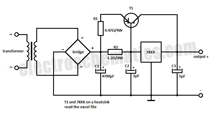
This voltage regulator extension circuit allows for an increase in output current up to 10 A. The T1 power transistor is configured with a resistor in the emitter. This voltage regulator extension circuit is designed to enhance the output current...