
VU Meter 2

A measurement circuit designed for level detection typically employs a combination of sensors and signal processing components to provide accurate readings. In this context, the circuit can utilize a variety of technologies, such as resistive, capacitive, or ultrasonic sensors, depending on the specific application requirements.
For instance, a resistive level sensor might consist of two electrodes placed at different heights within a tank. As the liquid level rises, the resistance between the electrodes changes, which can be measured and converted into a level indication. This method is straightforward but may be affected by the properties of the liquid, such as conductivity.
Alternatively, a capacitive level sensor operates by measuring the change in capacitance caused by the dielectric properties of the liquid. This type of sensor can be more versatile and less affected by the liquid's conductivity, making it suitable for a wider range of applications.
Ultrasonic level sensors utilize sound waves to measure the distance to the liquid surface. An ultrasonic transducer emits a pulse that reflects off the surface of the liquid and returns to the sensor. The time taken for the echo to return is proportional to the distance, allowing for precise level measurement. This method is non-contact and can be effective for various liquids and conditions.
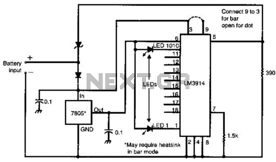
The output from these sensors is typically fed into an analog-to-digital converter (ADC) to process and interpret the signal. Microcontrollers or dedicated level monitoring ICs can be employed to analyze the digital data and provide a visual or digital output indicating the liquid level. Additionally, these circuits may include alarm systems or control outputs to manage pumps or valves based on the measured levels.
Overall, the design of a level measurement circuit must consider factors such as sensor type, environmental conditions, required accuracy, and response time to ensure reliable operation in its intended application.A circuit of measurement of level based on a typical application of National 🔗 External reference
Related Circuits
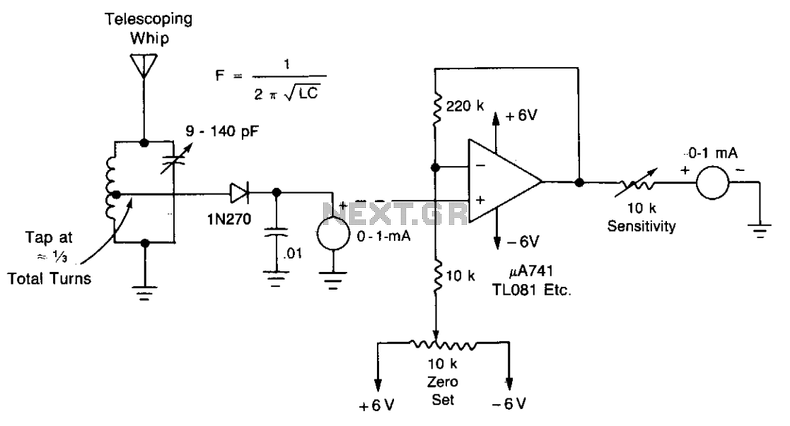
A field-strength meter with minimal components is presented here. For testing at greater distances, a DC amplifier can be added. It is recommended to use a single wire as the antenna. The field-strength meter is a simple yet effective device...
An analog meter typically does not exhibit high impedance due to the absence of a buffer circuit within its design. By incorporating active buffering, the input impedance of this circuit can be significantly enhanced. The integration of an active buffer...
Many amateur receivers are equipped with an S meter that does not operate logarithmically. The proposed circuit is intended to enhance such receivers. Although integrated circuits like the CA3089 or CA3189 are not commonly used today, they play a...
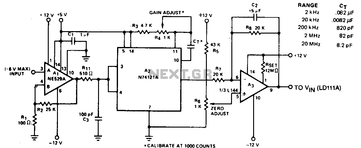
The circuit converts frequency to voltage by taking the average DC value of the pulses from the 74121 monostable multivibrator. The one-shot is triggered by the positive-going AC signal at the input of the 529 comparator. The amplifier functions...
CW is the simplest form of modulation. The output of the transmitter is switched on and off, typically to form the characters of the Morse code. CW transmitters are simple and inexpensive, and the transmitted CW signal doesn’t occupy...

This project involves a Regenerative Receiver designed for the 80-meter Amateur band, with the capability to tune from approximately 3 MHz to 10 MHz, suitable for Shortwave listeners. It shares a design lineage with the previously created "40-Meter Tweeter."...