
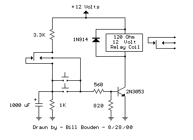
Water Activated Relay

The described circuit utilizes two transistors, T1 (2N2222A) and T2 (BC108), arranged in a compound configuration to enhance the overall current gain significantly. The 2N2222A is a popular NPN transistor known for its versatility and robustness, while the BC108 is a general-purpose NPN transistor that complements the 2N2222A in this application. The high gain of 15,400 indicates that even a small input current can be amplified to a much larger output current, making the circuit highly sensitive to small variations in input.
The design allows for a power supply voltage ranging from 4.5 to 15 volts, providing flexibility for various applications. The choice of a 5-volt relay, which typically requires 60 mA to activate, indicates that the circuit can be effectively used in low-power applications where the relay serves as a switch for controlling larger loads. The ability to activate the relay with a minimum input current of 4 µA signifies that the circuit is suitable for use with conductive fluids, such as tap or rainwater, which can easily provide the necessary current.
This circuit can be employed in applications such as liquid level sensing or fluid detection systems, where the presence of a conductive liquid can trigger a relay to control pumps, alarms, or other devices. The high sensitivity and low activation current make it ideal for monitoring systems that require minimal power consumption and reliable operation. Proper biasing and stabilization of the transistors are essential to ensure consistent performance, and additional components such as resistors and capacitors may be included in the schematic to enhance stability and response time.In his circuit Marin has used two transistors wired as a high gain compound pair. Transistor T1 may be a 2N2222A and T2 a BC108. The current gain will be the product of each transistors beta, which will be a minimum of 140 x 110 or 15400. The power supply used can be any voltage from 4. 5 to 15 volts, a typical 5 volt relay may require 60 mA to operate, in which case any fluid which passes a minimum current of 4 uA will activate the relay. This is easily achieved with tap or rain water. 🔗 External reference
Related Circuits
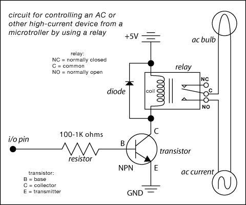
Here are some circuit diagrams for driving relays from a microcontroller. Ensure the use of a 5-volt relay (this refers to the coil, not the load circuit) and verify that the relay has a sufficient rating for the load...
Relays are commonly utilized as electrically controlled switches. Unlike transistors, the switch contacts of relays are electrically isolated from the control input. However, the power dissipation in a relay coil can be undesirable for battery-operated applications. The incorporation of...
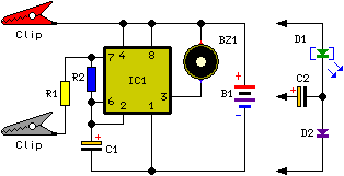
This circuit emits an intermittent beep or flashes an LED when the water level in a container reaches a predetermined height. It is designed to be mounted on top of the container, such as a plastic tank, using two...
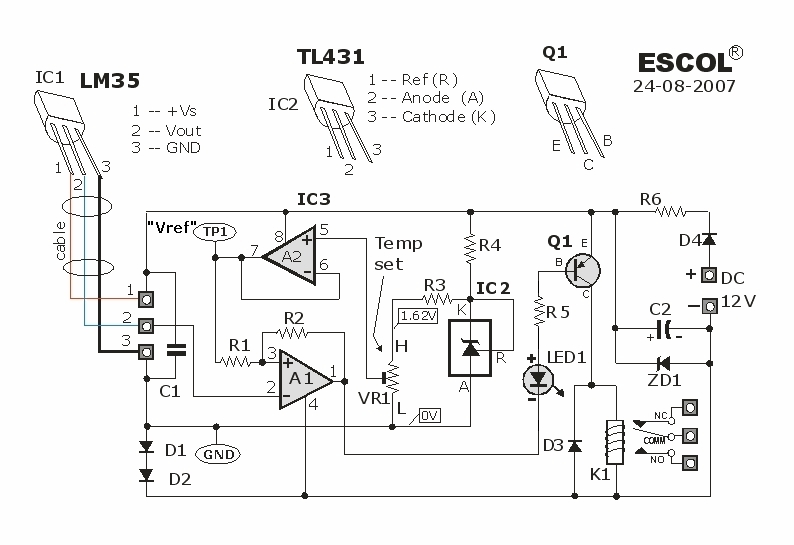
This temperature-controlled relay circuit is a simple yet highly accurate thermal control circuit that can be used in applications where automatic temperature regulation is required. The temperature-controlled relay circuit operates by monitoring the ambient temperature using a temperature sensor, such...
The circuit below requires a double pole, double throw relay in conjunction with a single transistor to allow toggling the relay with a momentary push button. One set of relay contacts is used to control the load, while the...

Rl limits input current while Ql acts as a current sink to protect IC1. D1 serves as a polarity protector. IC1 provides a triac output to trigger the main triac, TR1. The circuit consists of several key components that...