
Water Level Alert

The circuit operates on a 5V supply, ensuring compatibility with standard battery configurations. The use of a 555 CMOS timer in astable mode allows for a versatile frequency generation based on the variable resistance of the water, making it suitable for different container types and water levels. The crocodile clips acting as probes are a practical solution for non-invasive water level detection, and their ability to be extended with stiff wire enhances the circuit's adaptability for deeper tanks.
Resistors R1 and R2, along with capacitor C1, are critical in setting the oscillation frequency. The relationship between the resistance of water and the circuit's output frequency is a key feature, where lower resistance (higher water levels) results in higher frequencies, thus providing a clear signal of the water level status. The additional components for LED operation (C2, D1, and D2) are essential for ensuring that the LED receives adequate voltage, thus enhancing the circuit's functionality.
The circuit's low power consumption is particularly advantageous for applications requiring long-term monitoring without frequent battery replacements. The design eliminates the need for a manual power switch, further simplifying the user experience. Overall, this water level detection circuit combines efficiency, adaptability, and ease of use, making it suitable for various applications in both domestic and industrial settings.This circuit will emit an intermittent beep (or will flash a LED) when the water contained into a recipient has reached the desired level. It should be mounted on top of the recipient (e. g. a plastic tank) by means of two crocodile clips, acting also as probes. If a deeper sensing level is needed, the clips can be extended by means of two pieces o f stiff wire (see pictures). IC1, a 555 CMos timer chip, is wired as an astable multivibrator whose operating frequency is set by C1, R1 and R2, plus the resistance presented by water across the probes. If the resistance across the probes is zero (i. e. probes shorted), the output frequency will be about 3Hz and the sounder will beep (or the LED will flash) about three times per second.
As water usually presents a certain amount of resistance, the actual oscillation frequency will be lower: less than one beep/flash per second. As probes will be increasingly immersed in water, the resistance across them will decrease and the oscillation frequency of IC1 will increase.
This means that a rough aural or visual indication of the level reached by water will be available. If a LED is chosen as the alert, C2, D1 and D2 must be added to the circuit in order to double the output voltage, thus allowing proper LED operation (see the rightmost part of the schematics). Interesting features of this circuit are 1. 5V supply and ultra-low current consumption: 40 µA in stand-by and 0. 5mA in operation. This allows a single AAA alkaline cell to last several years and the saving of the power on/off switch.
If a LED alert is needed instead of the beeper, R2 value must be changed to 10K, the Piezo sounder can be omitted and D1, D2 and C2 must be added, as shown in the rightmost part of the schematics. 🔗 External reference
Related Circuits
This circuit is a Low-Light Level Drop Detector. It utilizes a self-biasing configuration to detect small changes in light levels. The Low-Light Level Drop Detector circuit is designed to sense minute variations in ambient light conditions, making it suitable for...
The microcontroller-based water level controller and motor protector manages the on and off states of the motor based on the water level in the overhead tank (OHT). It regulates the tank's water level through a microcontroller, thereby providing automatic...
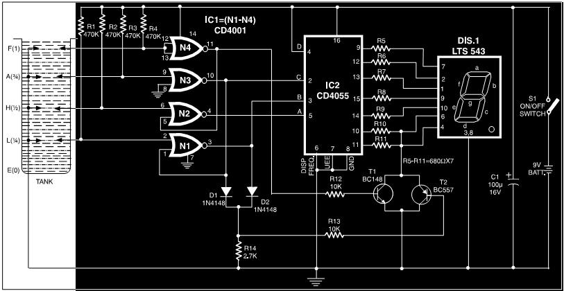
This circuit is a fluid level indicator that displays each level using meaningful English letters. It employs a seven-segment display to represent the letters E for empty, L for low, H for half, A for above average, and F...
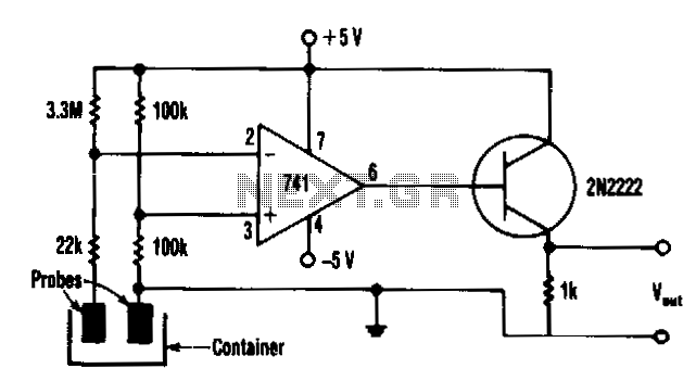
This monitor utilizes a common 741 op-amp configured as a comparator along with a low-cost non-transistor output driver. In the absence of liquid, a voltage of approximately 2.92 V is present at the inverting input (pin 2) of the...

A balanced Wheatstone bridge controls a JK flip-flop that utilizes an operational amplifier as an interface. This configuration subsequently drives a relay. Resistors R1 through R4 can be increased in value to enhance sensitivity. The circuit employs a balanced Wheatstone bridge,...

This transducer is from a humidifier and operates at 48 kHz. It includes a driver circuit and has easy access for modifications. The process of disassembling one of the two transducers suggests that the circuit board may be difficult...