
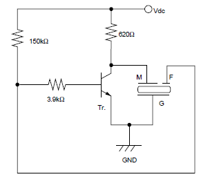
What determines the transmit frequency in this 555-based transmitter

The project involves designing a QRP (low-power) transmitter using the versatile 555 timer IC, which is favored for its ease of use and availability. The original design operates below the commercial AM band, necessitating modifications to achieve the desired frequency of approximately 1.8 MHz, which is the lower end of the 160-meter amateur radio band.
To set the operating frequency of the transmitter, the 555 timer can be configured in astable mode. In this configuration, the frequency is determined by the resistors and capacitors connected to the timer. The frequency (f) can be calculated using the formula:
f = 1.44 / ((R1 + 2R2) * C)
Where R1 and R2 are the resistances in ohms, and C is the capacitance in farads. To achieve the target frequency of 1.8 MHz, appropriate values for R1, R2, and C must be selected. For instance, using a capacitor value in the range of 10 nF and adjusting R1 and R2 accordingly can help reach the desired frequency.
Additionally, it is important to implement a low-pass filter following the output stage of the transmitter to minimize harmonics, which can interfere with other communications. A simple LC filter can be constructed using an inductor and a capacitor to ensure that only the fundamental frequency is transmitted.
In terms of power supply, a suitable voltage regulator may be used to provide a stable voltage to the 555 timer and associated components, ensuring reliable operation. Furthermore, a suitable antenna matching network could be incorporated to optimize the power transfer from the transmitter to the antenna, enhancing transmission efficiency.
Finally, safety precautions should be emphasized, especially when teaching students about RF transmission, to ensure compliance with local regulations and to promote responsible operating practices. This project not only serves as a practical application of electronics but also fosters an understanding of amateur radio principles among students.Planning on basing a QRP transmitter off of this instructables project, seeing as I have a veritable plethora of 555 ics in my shack toolbox. The problem is, this transmitter is designed to operate a bit below the commerical AM band. How is the general operating frequency being set I`d like to get it set around the 1. 8 mhz band (160 meters). Much help is appreciated, as I`m going to use this to teach the other kids in the ham radio club at my school how to build basic transmitters. Picture of circuit: 🔗 External reference
Related Circuits
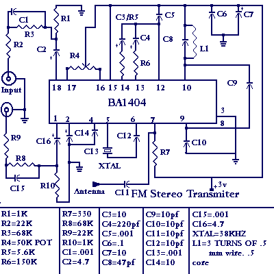
Construct a low-power FM transmitter using surface-mount devices (SMD) that can be received by a standard FM radio. The proposed low-power FM transmitter circuit utilizes surface-mount devices (SMD) to achieve compactness and efficiency. The primary components of the circuit include...
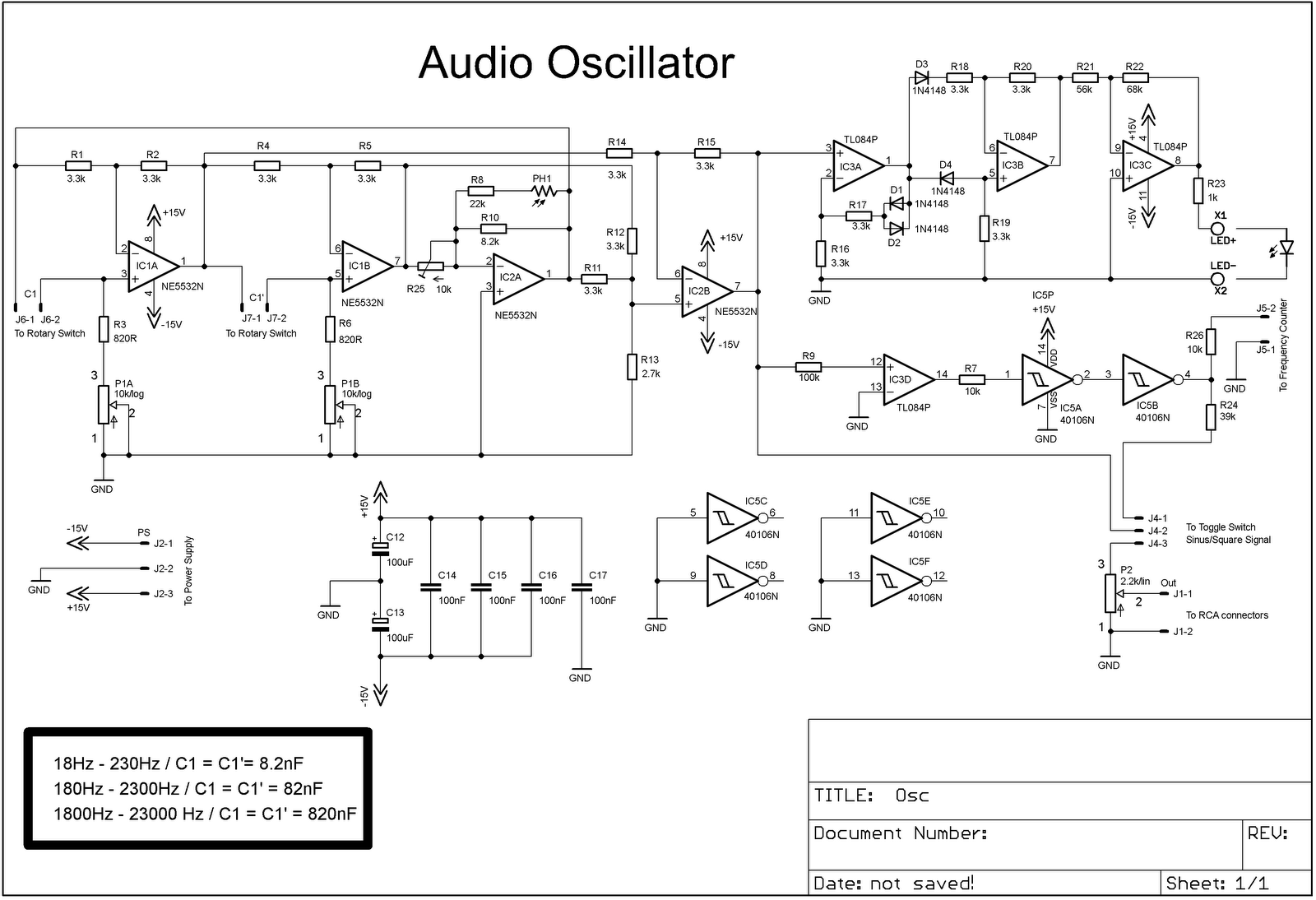
The project involves adding a DIY audio oscillator to a home workshop, which is essential for testing audio projects. While a basic oscillator is already available, it lacks a frequency counter. The design follows a schematic that provides a...
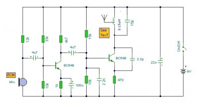
This is a mini FM transmitter circuit that utilizes two transistors. The audio sensitivity is notably high when paired with an ECM type microphone. The transmitter operates using a Hartley oscillator configuration. Typically, the capacitor in the tank circuit...
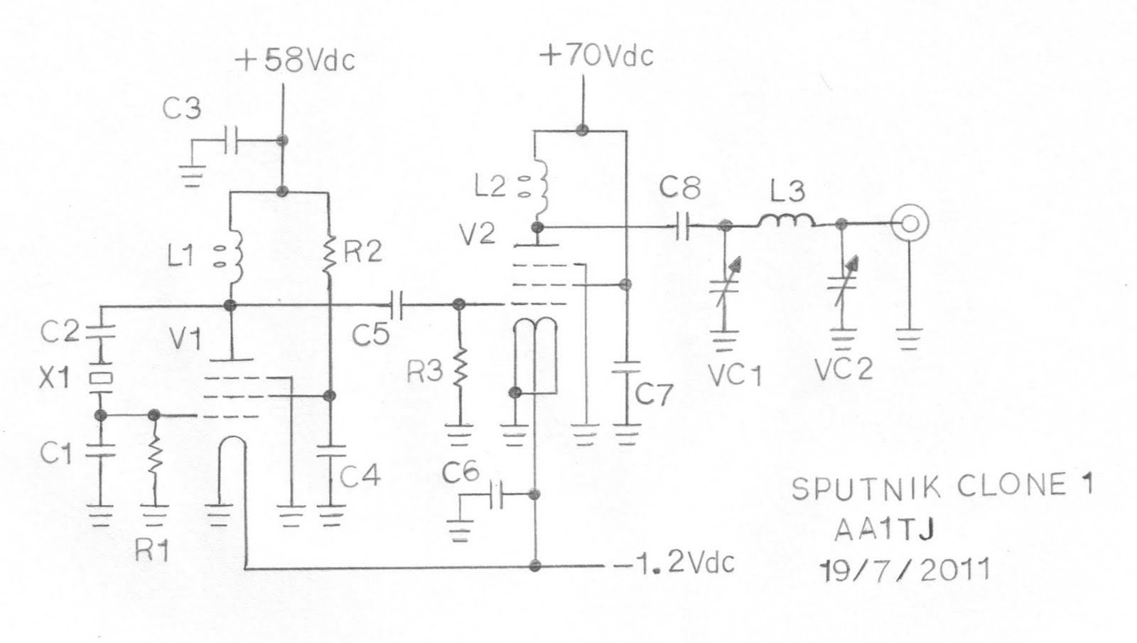
This document describes a prototype transmitter for the Sputnik QSO Party. The RF output power is 450 mW, with 70 V DC at 14.4 mA on the V2 anode. The screen current (G2) for V2 is 1.6 mA, while...
The piezoelectric effect operates in both directions: applying a voltage causes the piezo material to stretch, and conversely, stretching the material generates a voltage. This principle is utilized to create a feedback signal that drives the oscillator. The benefit...
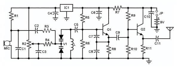
You'll find that this is a very easy project to build. It will transmit good quality sound in the FM band (88 - 108 MHz). One important item is that the IC chip operates on 3 volts DC. The...