
Whats the third wire on a piezo buzzer

The piezoelectric effect is a critical phenomenon in various electronic applications, particularly in sensors and actuators. When a voltage is applied to a piezoelectric material, it undergoes mechanical deformation, which can be harnessed for various purposes, such as generating sound in buzzers and speakers. Conversely, when mechanical stress is applied to the piezo material, it generates an electrical signal, making it useful in applications like pressure sensors or vibration detectors.
In the context of an oscillator circuit, the feedback mechanism is essential for maintaining stable oscillation at the desired frequency. The piezoelectric element can be integrated into a feedback loop, allowing it to self-adjust and operate at its natural resonance frequency. This self-resonance feature enhances performance by ensuring that the maximum acoustic output is achieved, making it particularly effective in audio applications.
In two-wire circuits, the design consideration becomes crucial, as the oscillator's frequency does not inherently align with the piezo's resonance frequency. The designer must carefully select circuit components, such as resistors and capacitors, to create a tuning network that matches the oscillator frequency to the resonance frequency of the piezo element. This tuning is often achieved through trial and error or by employing simulation tools to analyze the circuit's behavior.
In summary, understanding the piezoelectric effect and its implications for oscillator design is vital for optimizing performance in applications that rely on sound generation or sensing. Proper circuit design ensures that the piezo element operates efficiently, maximizing output while minimizing distortion or inefficiencies.The piezo effect works both ways: if you apply a voltage the piezo stretches, but also if it stretches it creates a voltage. This principle is used to create a feedback signal which drives the oscillator. The advantage of the self drive is that it will automagically work at its resonance frequency, where it produces the loudest sound.
In 2-wire circuits the oscillator`s frequency is independent of the piezo`s resonance frequency, and it`s the designer who has to make that they`re close. 🔗 External reference
Related Circuits
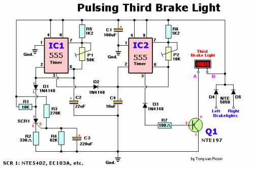
The circuit consists of two 555 timer oscillators configured in a dual timer arrangement, both set up in astable mode. Components include a 1N4148 diode and a 555 integrated circuit. The dual 555 timer circuit operates in astable mode, generating...

The transmitter for the wireless headphones is constructed using a CD4046 CMOS phase-locked loop, which is paired with a driver transistor and a set of infrared LEDs. While the CD4046 contains two phase comparators, a voltage-controlled oscillator (VCO), a...

This wireless stereo FM transmitter is constructed using a monolithic integrated circuit (IC). The internal architecture of this FM transmitter IC includes a stereo modulator that generates a stereo composite signal, an FM modulator that modulates a carrier frequency...
An 18-year-old electrical engineering student, Chris Rieger, has been developing his levitating light bulb project, aptly named the LevLight Project, for approximately six months. Recently, he shared images and a video of the project, which gained significant attention on...
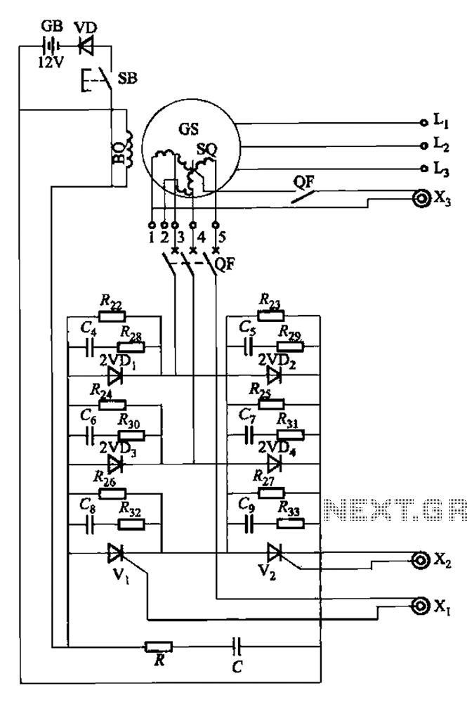
The setup is connected to separate stator windings of a harmonic generator, which leads to a thyristor rectifier supply for the third harmonic voltage, positioned after the motor field. The output voltage varies with changes in the winding harmonics...
Before proceeding with these steps, ensure that the software calibration and the basic procedures for checking audio circuit components have been completed. The audio circuit schematic diagram is preferred for easy tracking, and this method will aid in future...