
FM Stereo Transmitter with BA1404

This project involves building an FM transmitter capable of transmitting audio signals within the FM band, specifically between 88 MHz and 108 MHz. The core component of this circuit is an integrated circuit (IC) that operates at a supply voltage of 3 volts DC. Care must be taken to ensure that the supply voltage does not exceed 3.5 volts, as this could lead to irreversible damage to the IC.
The circuit utilizes a simple antenna, which can either be a standard telescopic antenna or a 2-foot length of wire, enabling effective transmission of the audio signals. The input signal to the circuit is expected to be in the millivolt range. To accommodate various audio sources, such as a Walkman or a portable CD player, it may be necessary to include additional potentiometers (pots) to adjust the input levels accordingly. This adjustment is crucial to prevent overdriving the IC, which could lead to distortion or damage.
For tuning the transmitter, the user should first set their FM radio to a quiet frequency where no station is broadcasting. The next step involves adjusting the trimmer capacitor (designated as C8 in the schematic) until the transmitted audio signal is audible through the radio. Once a strong signal is achieved, the resistor (R4) can be adjusted to ensure that the stereo signal indicator on the radio lights up, confirming that the transmission is in stereo mode.
To manage high input signals effectively, it is recommended to use two 15-turn potentiometers on the input lines. This configuration allows for fine-tuning of the signal levels, ensuring optimal performance without risking damage to the IC. The circuit can be further optimized for balance by using headphones to monitor the output.
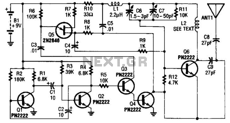
The inductor (L1) is an essential component in the circuit, consisting of three turns of 0.5 mm wire wound on a 5 mm ferrite core. This inductor plays a critical role in tuning and stabilizing the frequency of the transmitted signal, contributing to the overall performance of the transmitter.
Overall, this FM transmitter project is designed to be straightforward to assemble, providing a practical solution for transmitting audio wirelessly within the FM band while ensuring the integrity and safety of the circuit components.You'll find that this is a very easy project to build. It will transmit good quality sound in the FM band ( 88 - 108 mhz ). One inportant item is that the IC chip operates on 3 volts DC. The chip will get destroyed if it is operated on any voltage higher than 3.5 volts. The antenna can be a standard telescopic antenna or a 2 foot length of wire. The input is in the millivolt range and you may need to add additional pots for the inputs. I was able to use this circuit for a walkman and a portable CD player in my car. I used the headphone jack on both and varied the signal with the volume control. To adjust the circuit tune your FM radio to a quite spot then adjust the trimmer capacitor C8 until you hear the signal that you are transmiting. When you have a strong signal adjust the resistor R4 until the stereo signal indicator lights. If the input is to high of a signal you may over drive the IC chip. Use two 15 turn pots on the input signals to bring the level down. You can balance the signal by using headphones. The inductor L1 is 3 turns of .5 mm wire on a 5 mm ferrite core. 🔗 External reference
Related Circuits
This is a long-range stable FM transmitter circuit. The circuit utilizes an LM2950 5V voltage regulator IC in a TO-92 transistor package, which provides a stable 5V to the oscillator until the 9V battery voltage drops to 5.5 volts,...
The schematic presented is a circuit for a 555 tracking transmitter. The 555 timer is a well-known versatile integrated circuit utilized in various electronic projects. In the circuit described, this IC generates a tone that is transmitted through an...
The transmitter utilizes a 6BW6 vacuum tube to achieve an output power of approximately 5 watts. The circuit includes a component CI that is calibrated to produce the cleanest continuous wave (CW) note. The tuning capacitors C8 and C9...
The following schematic illustrates a 5.8W stereo power amplifier utilizing the Samsung IC KA2211. Each channel delivers a power output of 5.8W, resulting in a maximum combined output of 2 x 5.8W. The KA2211 is a dual audio power...
The transmitter operates within the VHF and VLF frequency ranges on TV channels, though it has not been tested for UHF frequencies. The modulated sound signal spans 5.5 to 6 MHz, which can be adjusted by tuning capacitor C5....
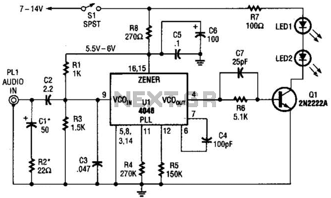
The transmitter for the wireless headphones is constructed using a CD4046 CMOS phase-locked loop, which is paired with a driver transistor and a set of infrared LEDs. While the CD4046 contains two phase comparators, a voltage-controlled oscillator (VCO), a...