
What is Microcontroller / PIC programer

The simple PIC programmer is designed to facilitate the programming of PIC microcontrollers, which are widely used in various electronic applications. The circuit typically requires a minimal number of components, making it an economical choice for hobbyists and engineers alike.
Key components of the programmer include a USB interface for power and communication, a microcontroller socket for the target PIC device, and essential passive components such as resistors and capacitors. The programmer may also utilize a standard 16-pin ICSP (In-Circuit Serial Programming) connector, which allows for easy connection to the microcontroller.
The circuit operates by sending programming signals from a computer via the USB port to the PIC microcontroller. The programmer typically employs a simple transistor-based level shifter to ensure that the voltage levels are compatible between the USB interface and the PIC microcontroller, which may operate at different voltage levels, such as 5V or 3.3V.
For assembly, a printed circuit board (PCB) or a breadboard can be used to mount the components. The connections should be made according to a schematic diagram, ensuring that each component is placed correctly to avoid any potential damage to the microcontroller. Once assembled, the programmer can be connected to a computer running compatible programming software, allowing users to upload code to the PIC microcontroller.
This low-cost solution is ideal for educational purposes, prototyping, and hobby projects, offering a practical way to engage with microcontroller programming without significant investment. Proper attention to detail during assembly and testing will ensure the reliability and effectiveness of the PIC programmer.How to build and use simple PIC programmer with very easy to find and extremely low cost parts. Total cost to build programmer is less than 1.5USD.. 🔗 External reference
Related Circuits
The following circuit illustrates a stepper motor controller. This circuit is based on the PIC16F84A integrated circuit. Features: a transistor is utilized to drive the motor. The stepper motor controller circuit employs the PIC16F84A microcontroller, which serves as the central...
This article describes a 2-Input alarm developed on the PIC LICK-1 Module using a Microchip PIC16F628-04. The program uses the internal 4MHz oscillator and if any other frequency is used, the timer values will need to be changed. A...
In the article you will find a description of the universal PIC programmer, which suggested the involvement of Jens Madsen Dyekjar. Program allows districts PIC12C5XX, 12C67X, 16C55X, 16C61, 16C62X, 16C71, 16C71X, 16C8X, 16F8X, serial EEPROM 24Cxx. It allows to...
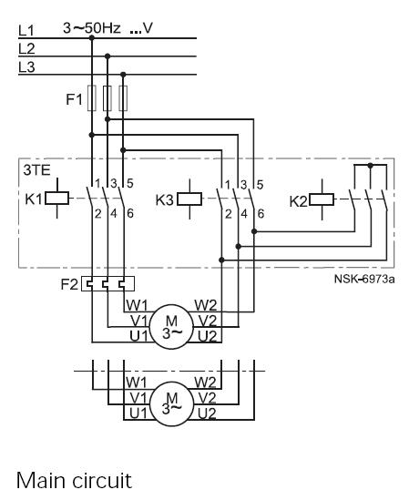
This method reduces starting current and starting torque. The device typically consists of three contactors, an overload relay, and a timer for setting the duration in the star position (starting position). The motor must be delta connected during normal...
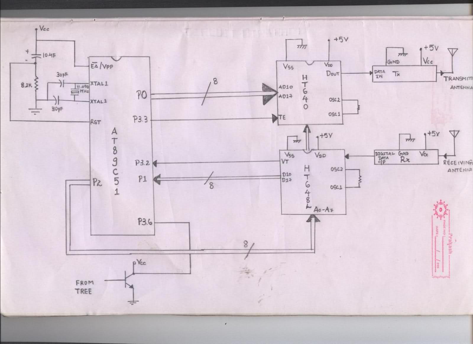
The issue arises when connecting the 8051 microcontroller to the HT640 encoder; the data sent is not received at the receiver. However, when the connections to the 8051 are removed, the transmission functions perfectly. This indicates that manual RF...
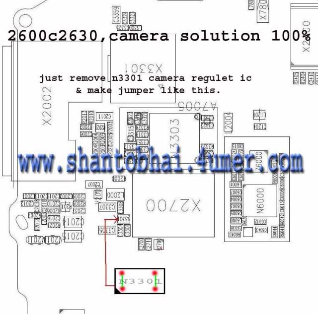
The camera operation failure on the Nokia 2630 has a similar solution to that of the Nokia 2600c, as both devices share the same circuit board. This issue is typically caused by hardware damage or a broken line on...