
Wireless Stereo FM Transmitter BA1404
This wireless stereo FM transmitter utilizes the BA1404 integrated circuit, which integrates multiple functionalities essential for FM transmission. The stereo modulator within the IC combines two audio channels into a single stereo composite signal, which is then fed into the FM modulator. This modulator alters the carrier frequency according to the composite signal, effectively encoding the audio information onto the RF signal. The RF amplifier boosts the modulated signal, enabling it to be transmitted over the airwaves through an antenna.
The transmitter is designed to operate within the FM broadcasting band of 75-108 MHz. This frequency range is suitable for short-range audio transmission, making the device ideal for applications such as wireless audio streaming from a personal device to an older radio system. The ability to connect to various audio sources, including MP3 and MP4 players, enhances its versatility.
For optimal performance, the operational frequency can be fine-tuned by adjusting the LC network connected to pin 10 of the BA1404 IC. A variable capacitor between 22-33 pF can replace the fixed 15 pF capacitor, allowing users to achieve the desired frequency response for their specific application. This feature is particularly useful for ensuring clear audio transmission and minimizing interference from other radio sources.
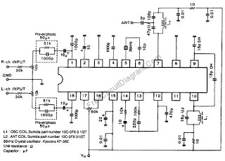
Power consumption is kept low, with the device requiring only a 1.5-3V power supply. This low-voltage requirement makes the transmitter particularly suitable for portable applications, as it can be easily powered by batteries. It is critical to adhere to the recommended voltage limits, as exceeding 3.5V could lead to circuit failure. Overall, the design of this wireless stereo FM transmitter provides an effective solution for audio transmission in various settings, combining ease of use with reliable performance.This Wireless Stereo FM Transmitter built from a monolithic IC. The internal structure of this FM transmitter integrated circuit consist of stereo modulator that creates a stereo composite signal, an FM modulator that modulate a carrier frequency with the composite signal, and an RF amplifier that provide enough power to be transmitted through ant enna. The core of this stereo FM transmitter is BA1404 integrated circuit chip. from ROHM. This FM transmitter is ideal for wireless microphone, or for audio interface and distribution for home or car appliance. For example, you can now play your portable mp3/mp4 player on your old car radio sound system that doesn`t have line-input plug.
This stereo FM transmitter chip is designed for 75-108 FM band, and you can adjust the operation by trimming the LC network connected to pin 10 of this IC chip. To ease the adjustment, you can use a 22-33p variable capacitor for the 15p capacitor connected to pin 10.
Finally, this stereo FM transmitter works with only 1. 5-3V power supply, ideal for battery operation. More than 3. 5V supply voltage could burn this FM transmitter circuit. 🔗 External reference
Related Circuits
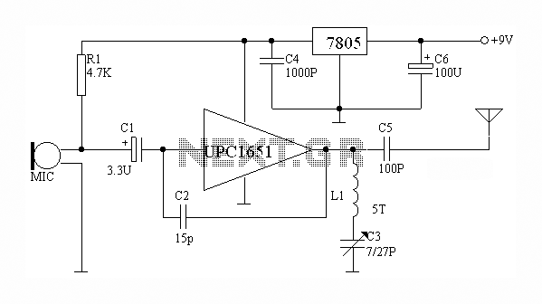
The circuit depicted utilizes the UPC1651 integrated circuit produced by NEC Corporation of Japan. It offers high gain and stability, ensuring optimal performance for microphones. The design incorporates an FM transmitter circuit. The system employs a flexible antenna measuring...
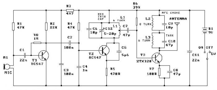
This FM transmitter project is a simple yet effective circuit capable of transmitting signals over a distance of up to 1 kilometer in open air conditions. The circuit employs an RF transistor in the output stage, along with two...
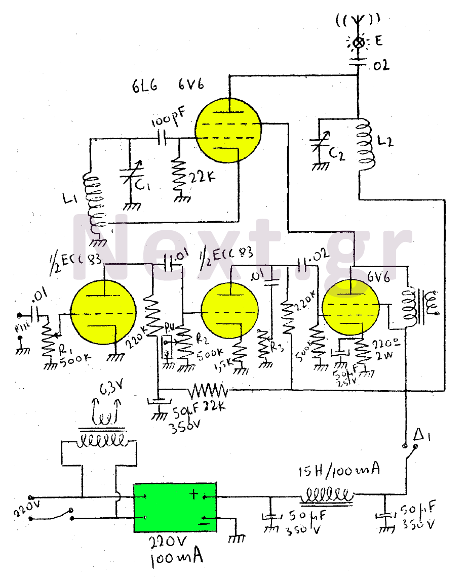
This circuit features a wearer assembly that includes a single lamp, either a 6V6 or 6L6, functioning as both an oscillator and an output amplifier. Coil L1 serves as the medium wave oscillation coil, while coil L2 is composed...
The first resistor on the left in the schematic is labeled as 68k. This value may change based on the microphone used. In this instance, a microphone from Digi-Key with a 1.5k output impedance was utilized, leading to the...
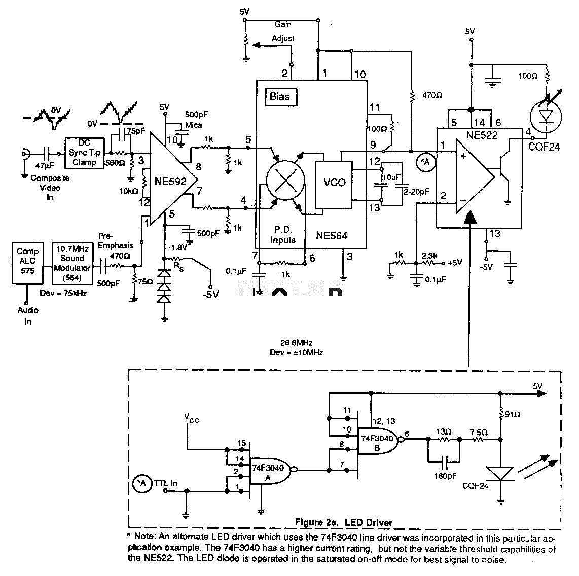
An alternate LED driver utilizing the 74F3040 line driver has been implemented in this application example. The 74F3040 offers a higher current rating but lacks the variable threshold capabilities found in the NE522. The LED diode operates in a...
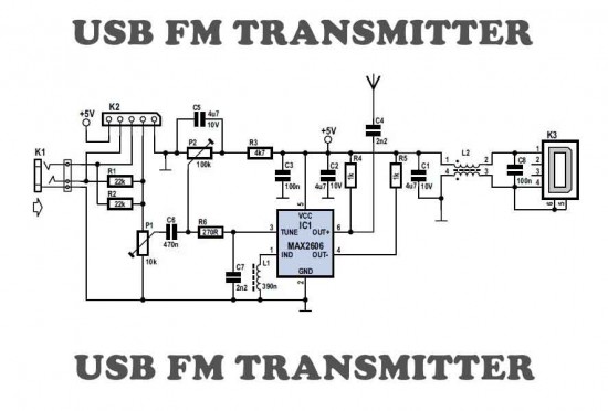
This is a simple USB FM transmitter designed to play audio files from an MP3 player or computer on a standard VHF FM radio. The USB FM transmitter operates by converting audio signals from a digital source, such as an...