
Whistle on / off switch

The op-amps are biased using a voltage divider of two 10K resistors so the output will be centered around half the supply voltage or 6 volts. The output of the second filter charges a 1uF cap at the base of a NPN transistor (2N3904 or similar). The emitter voltage is biased at 6.6 volts using the 3.3K and 2.7K resistors so that the transistor will conduct and trigger the flip flop when the peak signal from the filter reaches 8 volts. The 8 volt figure is the emitter voltage (6.6) plus the emitter base voltage drop (0.7) plus the diode drop (0.7). The sensitivity can be adjusted by changing the value of either the 2.7K or 3.3K resistors so that more or less signal amplitude is needed to trigger the flop flop.
The circuit integrates a CMOS toggle flip-flop with additional audio processing components to create a relay control mechanism activated by sound. The condenser microphone captures audio signals, producing a low voltage output that is amplified through two bandpass filters. These filters are specifically tuned to 1700 Hz, making the circuit responsive to a frequency that can be easily produced by whistling.
The design employs a quality factor (Q) of 8 for the filters, which ensures a narrow bandwidth around the center frequency, enhancing the circuit's sensitivity to the desired frequency while rejecting unwanted noise. The calculated resistor values for the filters are crucial for achieving the intended gain of approximately 65 per filter stage, resulting in a total gain of around 4000, suitable for processing the microphone's millivolt-level signals.
The op-amps used in the circuit are configured with a voltage divider biasing arrangement, ensuring that their output swings around 6 volts, effectively centering the signal for further processing. The output from the second filter is coupled to the base of an NPN transistor, which serves as a switch to toggle the flip-flop. The transistor's emitter is biased slightly higher than the output voltage to ensure it conducts when the signal exceeds a specific threshold, calculated to be 8 volts, taking into account the necessary voltage drops across the base-emitter junction and any diodes in the path.
Adjustments to the sensitivity of the circuit can be made by varying the resistor values in the emitter biasing network, allowing for fine-tuning based on environmental noise levels or the desired responsiveness to the whistled signal. This flexibility is essential for optimizing performance in various applications where sound-based triggering is required.This is an extension of the CMOS toggle flip flop circuit shown in the "Circuits controlling relays" section with the addition of two bandpass filters and condenser microphone so the relay can be toggled by whistling at it. The condender mic used is a PC board mount Radio Shack #270-090C. The filters are tuned to about 1700 Hz, or the third Ab above middle C on a piano keyboard which is a fairly easy note for me to whistle.
Resistor values for the filter can be computed using the three formulas below but we need to assume a gain and Q factor for the filter and the Q of the circuit must be greater than the square root of (Gain/2). The microphone produces only a couple millivolts so the overall gain needs to be around 4000 or around 65 for each filter. The Q or quality factor is the ratio of the center frequency to the bandwidth (-3dB points) and was chosen to be 8 which is greater than 5.7 which is the minimum value for a gain of 65.
Both capacitor values need to be the same for easy computation of the resistor values and were chosen to be 0.01uF which is a common value and usable at audio frequencies. From those assumptions, the resistor values can be worked out from the following formulas. R1 = Q/(G*C*2*Pi*F) = 8/(65*.01^-6*6.28*1700) = 1152 or 1.1K R2 = Q / ((2*Q^2)-G)*C*2*Pi*F) = 8/((128-65)*.01^-6*6.28*1700)= 1189 or 1.2K R3 = (2*Q)/(C*2*Pi*F) = 16/(.01^6*6.28*1700) = 150K The op-amps are biased using a voltage divider of two 10K resistors so the output will be centered around half the supply voltage or 6 volts.
The output of the second filter charges a 1uF cap at the base of a NPN transistor (2N3904 or similar). The emitter voltage is biased at 6.6 volts using the 3.3K and 2.7K resistors so that the transistor will conduct and trigger the flip flop when the peak signal from the filter reaches 8 volts.
The 8 volt figure is the emitter voltage (6.6) plus the emitter base voltage drop (0.7) plus the diode drop (0.7). The sensitivity can be adjusted by changing the value of either the 2.7K or 3.3K resistors so that more or less signal amplitude is needed to trigger the flop flop.
🔗 External reference
Related Circuits
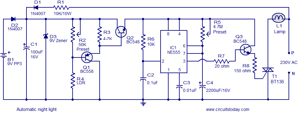
A simple and inexpensive automatic night light circuit designed using the timer IC NE555, which extinguishes after a preset time. This time can also be adjusted. The automatic night light circuit utilizes the NE555 timer IC configured in monostable mode....
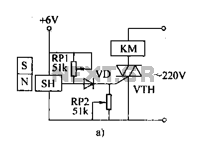
The automatic weapon features a magnetic switch circuit that is simple, reliable, has a low failure rate, and offers good versatility. It can be used for output performance or converted into mechanical displacement applications. The circuit diagram utilizes a...
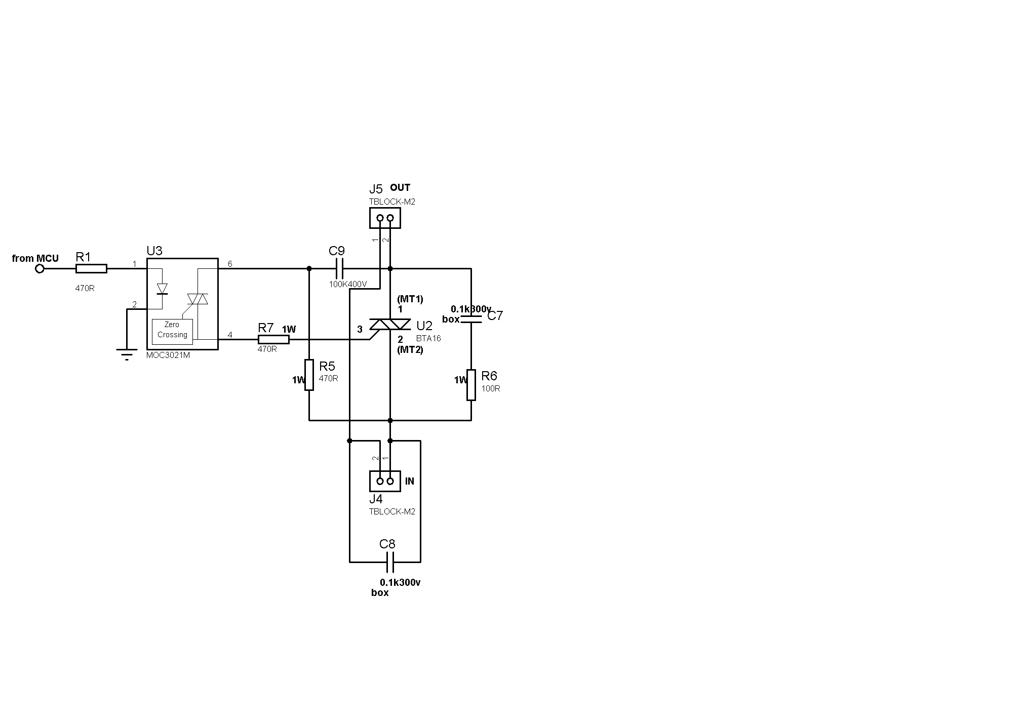
Sufficient snubbering appears to be present around the TRIAC, which should mitigate DV/DT-based switching, preventing the TRIAC from inadvertently turning on due to noise on the gate lead. The issue likely resides on the microcontroller side. When the microcontroller...
A one-inch reed switch with 40 turns effectively activates with the current flowing through a 150-watt lamp (approximately 625 mA), though larger reed switches may necessitate additional turns. If the master appliance draws less current, which is uncommon for...
The Elect. Sel. 8 is a simple circuit, with a choice of 8 sources of any sort, of 8 independent switches. Each switch corresponding with a relay for example the switch S1 activates the RL1 etc. The uses of...
How often does it happen that a user closes down Windows and then forgets to turn off the computer? This circuit addresses that issue by automatically powering off the computer after Windows has been shut down. This circuit operates by...