
Whistle Switch

The whistle switch operates by detecting audio signals, specifically the sound of a whistle, and using these signals to control an appliance. The core functionality involves several key components: a microphone, an audio amplifier, a frequency-selective circuit, and a control mechanism for the appliance.
The microphone captures the sound waves produced by a whistle. It is essential that the microphone is sensitive enough to pick up the specific frequency of the whistle. Following the microphone, an audio amplifier is employed to boost the microphone's output. This amplifier must be designed to provide sufficient gain to convert the relatively weak audio signal into a stronger signal that can be processed further. The output of the audio amplifier should ideally produce square wave signals from the input noise to ensure that the subsequent stages can effectively detect the whistle sound.
Instead of using an LC tuned circuit, which can be bulky and less flexible, an active bandpass filter can be integrated. This filter is tuned to the frequency range where the user typically whistles, allowing for more effective noise filtering and enhancing the detection of the desired signal. The active bandpass filter can be constructed using operational amplifiers and passive components, providing a compact solution that can be easily adjusted for different whistle frequencies.
The detection mechanism should incorporate a comparator or a microcontroller that can interpret the filtered signals. The comparator compares the amplified and filtered signal against a predefined threshold to determine if a whistle has occurred. The detector's response time is critical; it should have a slow attach time to avoid false triggering from transient noises while maintaining a fast release time to ensure that the appliance can be turned off quickly after the whistle ceases.
Finally, the output from the detector can be connected to a relay or a transistor switch that controls the appliance. This stage must be capable of handling the power requirements of the appliance being controlled, ensuring safe and reliable operation.
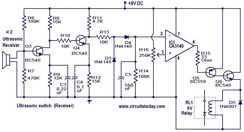
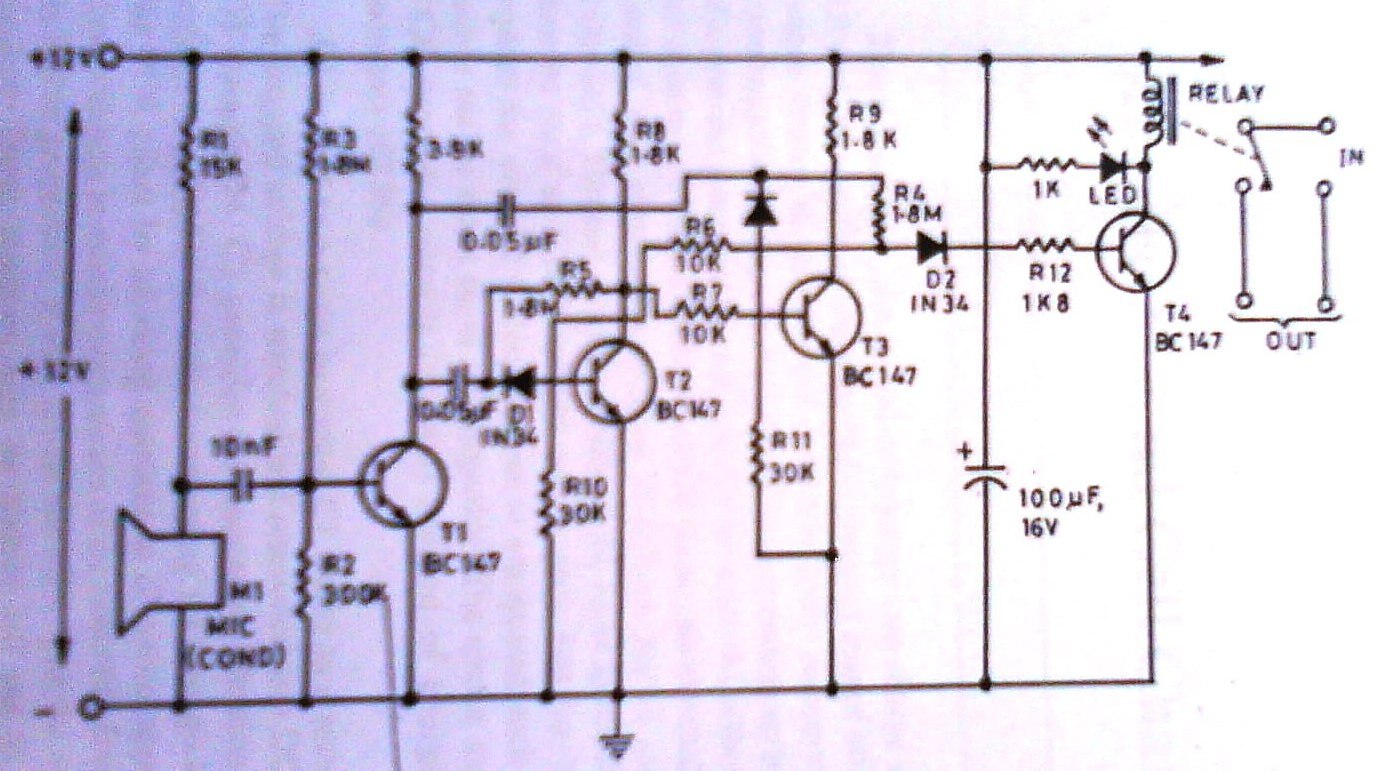
In summary, the modern whistle switch design can enhance the original concept by utilizing contemporary components such as active filters and microcontrollers, improving performance and reliability while maintaining the core functionality of the original design.The whistle switch allows you to turn on, or off, an appliance by whistling at it. I originally built the whistle switch in 1974. Do not attempt to duplicate it from the schematic below, but instead, understand the functions and duplicate these functions with more modern components. The audio amp, after the microphone, should have enough gain to produce square waves from input noise. The LC tuned circuit can be replaced by an active bandpass filter, at the frequency that you whistle the easiest.
The detector has a slow attach, fast d 🔗 External reference
Related Circuits
A two-line intercom with a telephone changeover switch. This circuit can connect two telephones in parallel and function as a 2-line intercom. Typically, a single telephone is connected to a. The two-line intercom circuit is designed to facilitate communication between...
The transmitter section of the circuit is built around IC1 (NE 555), which is configured as an astable multivibrator operating at 40 kHz. The output from IC1 is amplified by a complementary pair of transistors (Q1 and Q2) and...

The 2N4391 features a low ON resistance of 30 ohms and a high OFF impedance of less than 0 pF when in the off state. With appropriate layout and an optimal switch configuration, the stated performance can be easily...
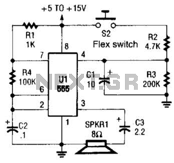
This is a cross-sectional diagram of a flex switch. They can be used as pushbuttons or even position sensors. This schematic diagram shows an oscillator, which is used as an alarm sounder, triggered by a flex switch. The flex switch...
This project involves a simple touch switch circuit that can also be utilized to activate a relay instead of an LED and resistor. The circuit exhibits high sensitivity due to the use of two transistors configured as a Darlington...
This clap switch can turn on and off a light, fan, music system, or alarm—virtually any gadget—at the sound of a clap. The most remarkable feature of this design is its ability to provide efficient two-state control without the...