
WIDE RANGE AC VOLTMETER

The circuit employs a diode bridge rectifier, which consists of four diodes arranged in a specific configuration to convert alternating current (AC) to direct current (DC). This configuration allows for efficient rectification, providing a unidirectional output voltage regardless of the polarity of the input AC signal.
In this setup, the operational amplifier (op-amp) plays a critical role in maintaining the accuracy of the output voltage. It is connected in a feedback loop that includes the diode bridge, allowing it to sense and compensate for any offset voltage that may arise due to the characteristics of the diodes or the circuit itself. The op-amp adjusts its output to ensure that the rectified voltage remains stable and within the desired range, thereby enhancing the overall performance of the circuit.
The feedback network is essential for achieving high precision in applications where the output voltage must closely match a specified reference value. The combination of the diode bridge and the op-amp allows for effective filtering and regulation of the rectified voltage, making this circuit suitable for various electronic applications, including power supplies, signal conditioning, and measurement systems.
Overall, the integration of a diode bridge with an operational amplifier in a feedback configuration is a robust solution for rectifying AC signals while compensating for any inherent offset voltages, ensuring reliable and accurate performance in electronic circuits.In this circuit, a diode bridge is used as a meter rectifier. The offset voltage is compensated for by the op amp, since the bridge is in the feedback network. 🔗 External reference
Related Circuits
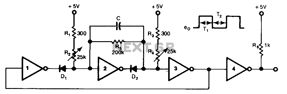
This free-running TTL square-wave oscillator features a variable frequency output spanning a 20:1 range or better. It utilizes four of the six inverters in an SN7404 chip along with additional components. The frequency of oscillation is dictated by the...
The circuit was designed to create a high-impedance voltmeter capable of measuring Direct Current (DC) voltages across various types of circuits. The high-impedance voltmeter circuit typically employs operational amplifiers (op-amps) configured in a non-inverting arrangement to ensure minimal loading on...
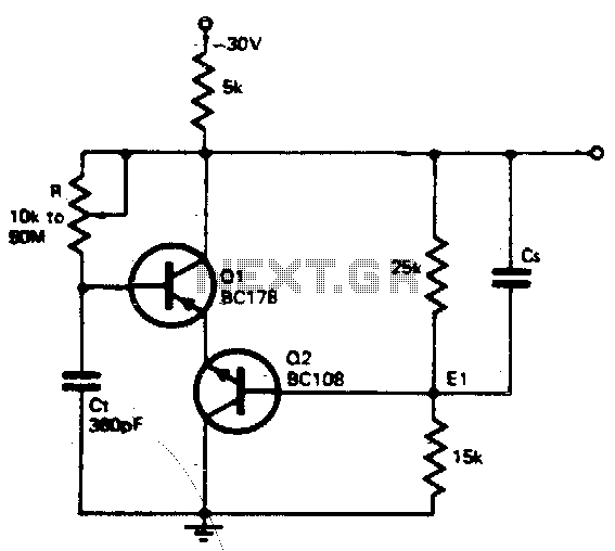
The timing resistor R can be adjusted to any value between 10 kΩ and 50 MΩ to achieve a frequency range from 400 kHz to 100 Hz. Connecting the timing resistor to the collector of Q1 ensures that Q1...
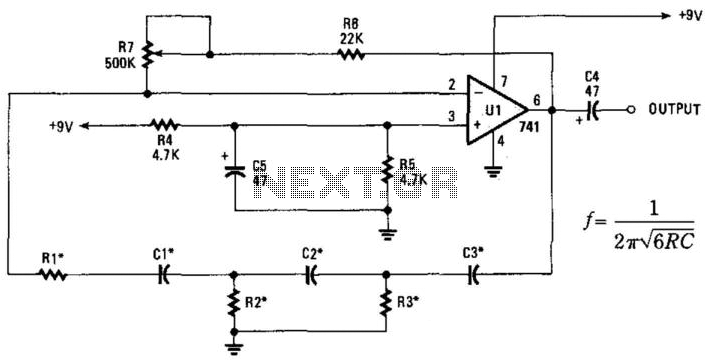
This phase-shift oscillator is suitable for audio oscillator applications. Adjust R7 to achieve a good sine wave. An amplifier gain of 29 is necessary for oscillation. If C=C1=C2=C3 and R=R1=R2=R3: Typically, R will range from 1 to 100 kOhm...
Two single-ended circuits are connected back to back to provide a differential input. This circuit not only features a differential input but also exhibits high impedance, significantly higher than that of an analog ammeter without this circuit. A schematic...
Measuring inductance is important for creating hand-made inductors, particularly when engaging in do-it-yourself (DIY) coil winding. An inductance meter adapter can facilitate this process. An inductance meter adapter is a vital tool for accurately measuring the inductance of coils and...