
Wideband Test Amplifier

This single-stage amplifier circuit is an essential component for enhancing signal levels in various testing applications. The choice of transistors, either the 2N2222 or 2N3904, provides flexibility and reliability, as both are widely used in low-power amplification due to their favorable characteristics, including high gain and low noise.
The transformer T1, constructed with an Amidon Associates FT-23-43 core, plays a crucial role in the circuit by providing impedance matching and signal isolation. The primary winding consists of 17 turns of #26 wire, while the secondary winding features 6 turns. This configuration allows for effective voltage transformation, enabling the amplifier to boost the input signal to a level suitable for the output monitoring device.
The output jack J3 is specifically designed for connecting to lower-level monitoring devices, such as a receiver frequency counter or a spectrum analyzer. This output provides a convenient means to observe the amplified signal without introducing significant loading effects on the circuit. The design ensures that the amplifier maintains signal integrity while delivering sufficient output for accurate measurements.
Overall, this single-stage amplifier circuit is a valuable tool for engineers and technicians working with test instruments, offering an efficient solution for signal amplification and monitoring. This single-stage amplifier (using a 2N2222 or 2N3904 general-purpose transistor) is useful for interfacing test in struments. T1 is an Amidon Associates FT-23-43 core wound with 17 and 6 turns of #26 wire. J3 is a lower-level output for a monitoring device (such as a receiver frequency counter or spectrum analyzer).
Related Circuits
The TPS3803 and TPS3805 families of supervisory circuits offer circuit initialization and timing supervision, mainly for digital signal processors (DSPs) and processor-based systems. The TPS3803G15 device features a fixed-sense threshold voltage (VIT) determined by an internal voltage divider, while...
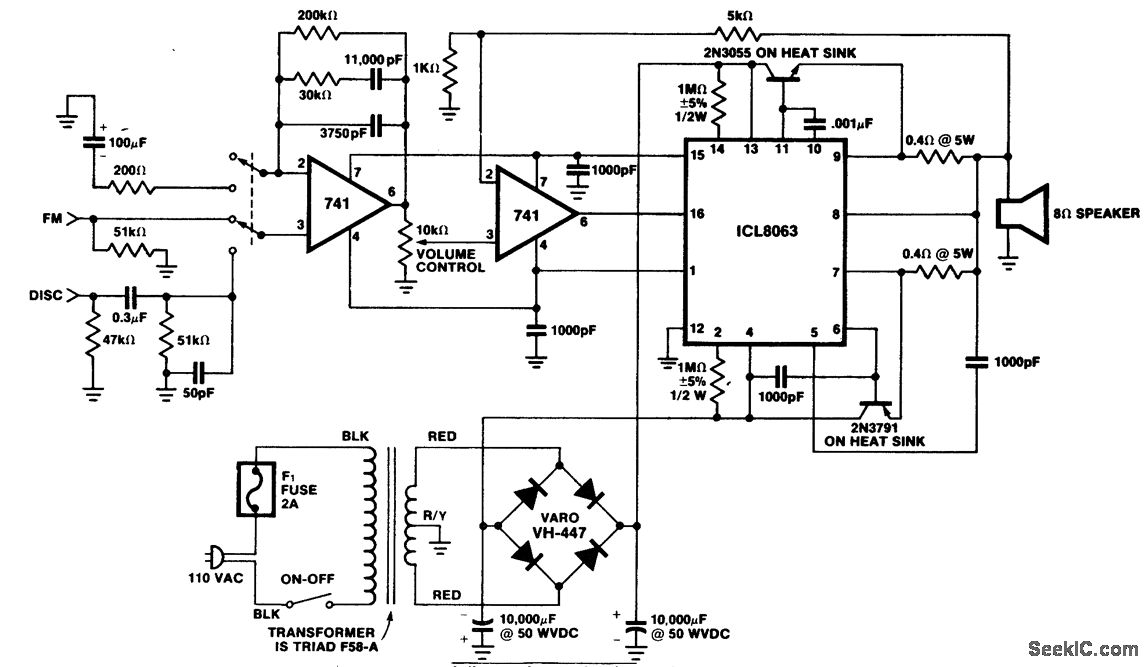
A 50-watt PMS hi-fi amplifier designed for an 8-ohm load. This circuit provides approximately 56 volts peak-to-peak across the 8-ohm load. The distortion level is around 1% at 20 kHz. A ganged switch at the input allows for the...
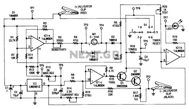
This circuit measures the cold cranking amps of a battery by discharging the surface charge and then assessing the internal resistance. This method provides a more accurate measurement than merely observing the instantaneous voltage drop under load. A constant-current...
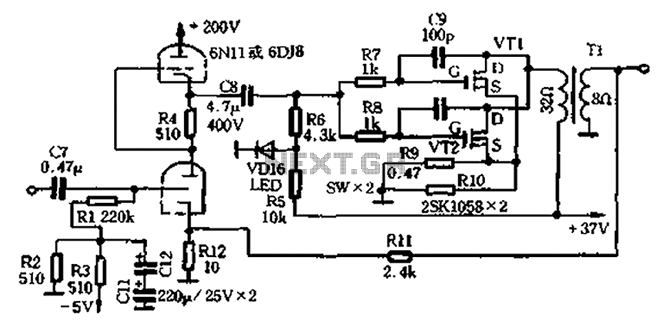
The amplifier circuit illustrated in Figure 2-25 features the following: (1) It utilizes a class 6N11 tube for parallel push-pull amplification, providing high-frequency response and an excellent signal-to-noise ratio. (2) The final stage of the semiconductor amplifier does not...
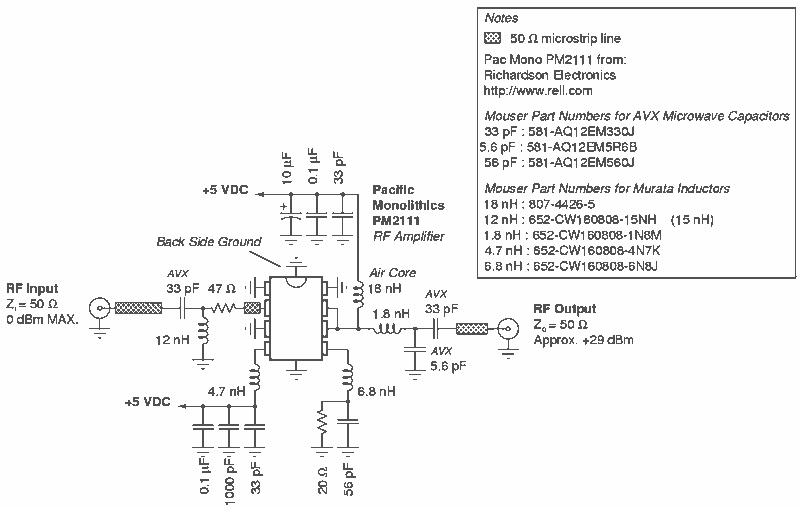
RF Power Amplifier 1 Watt. Jams Cellular Downlink Band: 800-950 MHz. The RF power amplifier described is designed to operate within the cellular downlink frequency range of 800 to 950 MHz, delivering an output power of 1 Watt. Such amplifiers...

This design concept addresses a major challenge associated with the use of photodiodes in high-speed applications such as barcode scanners, CD-ROMs, and DVDs, specifically the high output capacitance of the diode. The critical component in the circuit is the...