
Wideband UHF Amplifier - Antenna TV Amplifier Circuit

The UHF wideband amplifier is designed to enhance weak television signals in the specified frequency range. Its architecture typically includes a series of low-noise amplifying stages to achieve the specified gain while maintaining signal integrity. The choice of SMD capacitors (C1, C2, C6, and C7) is crucial, as these components help filter out unwanted frequencies and stabilize the amplifier's performance.
The metal enclosure serves multiple purposes: it protects sensitive electronic components from external interference and environmental factors, and it helps to minimize electromagnetic interference (EMI) that could degrade the amplifier's performance. Proper grounding of the enclosure is essential to ensure effective shielding.
The power supply, rated at 12V, should be stabilized to prevent voltage fluctuations that could affect the amplifier's performance. The inclusion of a 10 to 100 µH coil on the power line is a critical design feature; it acts as an inductor that filters out high-frequency noise from the power supply, ensuring that only the desired signals are amplified.
Connecting the amplifier to the TV set through a coupling capacitor is a common practice in RF design. This capacitor allows AC signals to pass while blocking DC components, preventing potential damage to the TV’s circuitry. The amplifier should be carefully calibrated to optimize the gain and ensure that the output signal is within the acceptable range for the connected TV.
In summary, the design and implementation of a UHF wideband amplifier involve careful consideration of component selection, housing, power supply design, and signal coupling techniques to achieve reliable performance in enhancing weak TV signals.This UHF wideband amplifier(Ultra High Frequency amplifier) has a total gain of 10 to 15 dB in the 400 850 MHz domain frequency so it can be used where the tv signal is weak. For this UHF antenna tv amplifier to work correctly you need to cut the components pins as short as possible.
C1, C2, C6, C7 are SMD type ( surface mounted ). This antenn a tv amplifier or uhf wideband amplifier need to be build inside of a metal box and then connected close to the tv antenna. The power supply is a simple 12V stabilized source. The antenna tv amplifier can be connected directly to the power supply thru coaxial cable of the tv antenna but you need a 10 100uH coil on the alimentation line.
The tv set will be connected to the uhf amplifier thru a small coupling capacitor. 🔗 External reference
Related Circuits
An RF force amplifier for FM is essential for amateurs looking to enhance small transmitters, whether they are homemade or commercially available. The presented circuit can deliver 50-60W of RF power with an input control of 15-20W within the...
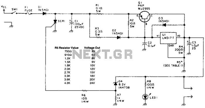
A laptop computer power supply that provides a 9-V output, includes crowbar overvoltage protection, and operates from a 12-V input supply is described. The input supply voltage must be at least 3.6 V above the desired output voltage. The...
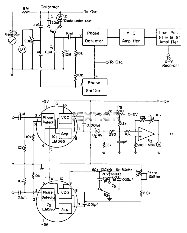
The application of automatic plotters for measuring the capacitance-voltage characteristics of solar Schottky gate diodes is discussed. A diode is connected as illustrated below. The integrated circuit (IC) generates a square wave output phase. Additionally, resistor R3 can be...
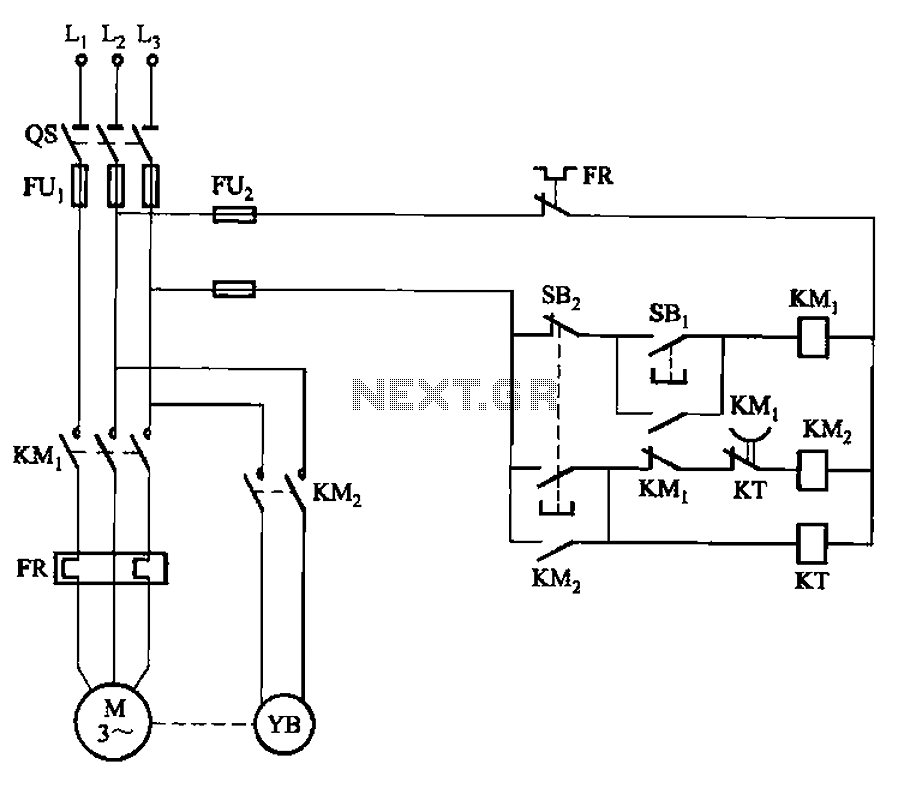
The circuit illustrated in Figure 3-123 operates as follows: When the stop button SBz is pressed, contact KMi releases, cutting off power to the motor. Simultaneously, KMz is activated, engaging the electromagnetic brake YB to hold the motor in...
PWM waveforms are widely utilized to regulate the speed of DC motors. The duty cycle of the digital waveform can be established either through an adjustable analog voltage level (as seen in a NE555-based PWM generator) or through digital...
It is the essential continuity of circuits Sel 8 Sources and Up/Down Sel 8 Sources, but can work and autonomously, collaborating with any suitable circuit of control. The Relay 1-8 can be 6-24v DC. For current of collector of...