
Wien-Bridge-Based Oscillator With Very Low Distortion

The oscillator circuit described is a sophisticated design that enhances the performance of the traditional Wien bridge oscillator by employing modern electronic components. The use of a photocell allows for light-dependent modulation of the circuit's output, which contributes to its stability and accuracy. The common-mode suppression circuit plays a crucial role in minimizing noise and interference, ensuring that the output signal remains clean and precise.
In this configuration, the traditional lamp, which is typically used in Wien bridge oscillators to provide feedback and stabilize the amplitude of oscillation, has been replaced with an electronic component. This substitution not only improves reliability by eliminating mechanical wear associated with lamps but also increases the overall efficiency of the oscillator. The electronic equivalent can be finely tuned to optimize performance, leading to a significant reduction in distortion levels to as low as 0.0003%.
The oscillator operates by generating a sine wave output, which is essential in various applications such as signal processing, audio synthesis, and telecommunications. The photocell's responsiveness to ambient light levels allows for dynamic adjustments in the oscillator's frequency and amplitude, making it suitable for environments where conditions may change.
Overall, this advanced oscillator circuit represents a significant evolution in oscillator technology, combining innovative components and design techniques to achieve superior performance metrics. This complex oscillator circuit uses a photocell and common-mode-suppression circuitr y to achieve distortion of 0.0003%. This oscillator circuit replaces the lamp in the traditional Wien bridge with an electronic equivalent.
Related Circuits
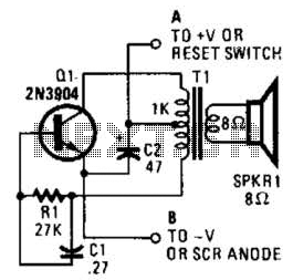
This is a simple low-level noise maker that is ideally suited for certain alarm applications. When the sounder is located in another part of the building, the sound level is loud enough to be heard but is not loud...
The 27MHz quartz crystal oscillator circuit is illustrated in figure 1. The biasing circuit consists of resistors R1, R2, and R3, while C6 serves as the bypass capacitor. The partial voltage circuit includes capacitors C1, C2, C3, and C4...

The MAX2620 integrates a low-noise oscillator with two output buffers in a cost-effective, plastic surface-mount, ultra-small uMAX package. This device combines functions that are typically achieved with discrete components. The MAX2620 is designed for applications requiring precise frequency generation with...
This is a simple scheme for a bridge oscillator. It provides a nice sinusoidal signal. This type of oscillator uses an op-amp. The weakening of the oscillating member (R1, R2, C1, C2) is 3x. To compensate, the attenuated signal...
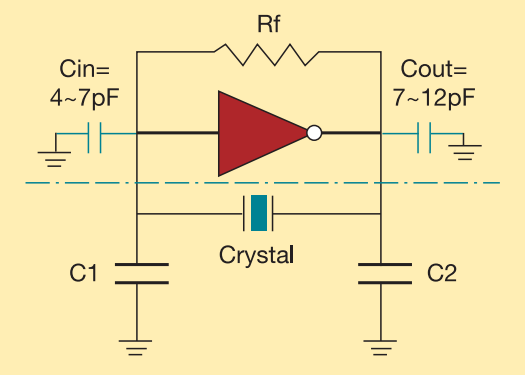
The crystal used in the topology of Figure 1 can be either a fundamental AT-CUT or BT-CUT. A BT-CUT crystal has poor frequency stability over temperature compared to an AT-CUT. This topology uses a parallel crystal and not a...
The wire connected to the 5V pin is linked to the positive pins of the breadboard, which are not connected to any other components. There are no additional connections on the positive column. While this may seem like a...