
RC feedback oscillators

RC oscillators are fundamental circuit designs utilized in various applications for generating periodic waveforms, particularly in the audio frequency range. The basic principle of operation involves the charging and discharging of capacitors through resistors, which creates a time delay that ultimately determines the frequency of oscillation.
In a typical RC oscillator circuit, one of the most common configurations is the Wien Bridge oscillator. This configuration consists of a bridge circuit made up of two resistors and two capacitors arranged in such a way that it provides a feedback loop necessary for oscillation. The frequency of oscillation is determined by the values of the resistors and capacitors in the circuit, specifically calculated using the formula:
\[ f = \frac{1}{2\pi R C} \]
where \( f \) is the frequency, \( R \) is the resistance, and \( C \) is the capacitance.
Another popular type of RC oscillator is the phase-shift oscillator, which employs multiple RC networks to achieve the necessary phase shift for oscillation. Typically, three or more RC stages are used to provide a total phase shift of 180 degrees, combined with an additional 180-degree phase shift from an inverting amplifier, resulting in a total of 360 degrees or a full cycle.
RC oscillators are widely used in audio applications, signal generators, tone generators, and various timing circuits. They are valued for their simplicity, low cost, and ease of implementation. Furthermore, the frequency can be easily adjusted by changing the resistor or capacitor values, making them versatile for different applications.
In summary, RC oscillators are essential components in electronics, providing reliable and efficient means of generating audio-frequency signals through the interaction of resistors and capacitors in various configurations.RC oscillators employ resistors and capacitors and are used to generate low or audio-frequency signals. Hence they are also known as audio-frequency (A.F) oscillators.. 🔗 External reference
Related Circuits
The transformer OCL and capacitor C1 create a tank circuit, which is coupled with sufficient turns to drive the grid in the lower left-hand winding. The output circuit is connected through a separate winding. For optimal waveform characteristics in...
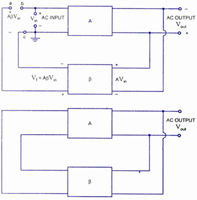
A feedback amplifier with a closed-loop gain, Af, greater than unity can be achieved through the use of positive feedback. This condition also fulfills the phase requirement, leading to the operation of an oscillator circuit. An oscillator circuit generates...
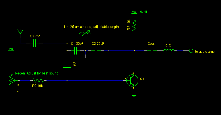
A common emitter Colpitts oscillator was constructed using variable capacitors for C1 and C2, and a few turns of wire wrapped around a pencil for the inductor L. Resistors R1 and R2 were replaced with a trimmer potentiometer to...
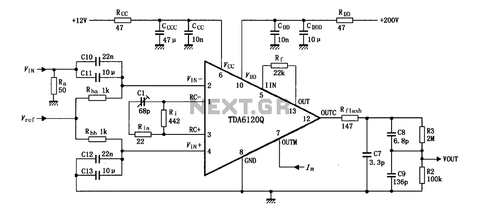
Feedback has indicated that the TDA6120Q test circuit, as shown in the figure, utilizes an input signal (Vi) composed of resistors Ra and capacitors C10 and C11, which are fed into the TDA6120Q at pins 2, 3, and 4....
One application of this handy circuit is a graphic equalizer, created by feeding a signal to a number of parallel band-pass filters each tuned to a different frequency; typically octaves apart. Then, you can adjust the strength in each...
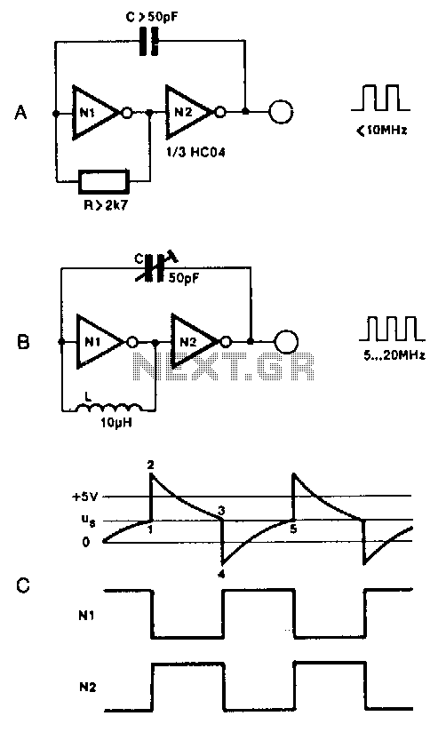
Two inverters, one resistor, and one capacitor are sufficient to create an HC(T)-based oscillator that operates reliably up to approximately 10 MHz. The use of two HC inverters results in a fairly symmetrical rectangular output signal. In this configuration,...