
wireless picaxe based water tank level sensor

The schematic for the water tank level meter consists of several key components integrated to ensure accurate measurement and transmission of water levels. The MPX-2010DP silicon pressure sensor is the primary sensing element, providing a pressure output proportional to the water level in the tank. The sensor's output is connected to an instrumentation amplifier, which enhances the weak signal from the sensor, allowing for more precise readings. The amplified signal is then fed into the 18X PICAXE microcontroller, which performs analog-to-digital conversion, translating the analog voltage into a digital format suitable for processing.
The microcontroller is programmed to read the digital values from the pressure sensor at regular intervals. It also controls the 433MHz RF transmitter, which is responsible for sending the water level data, along with the battery voltage, to the remote base station. The base station is equipped with an RF receiver that captures the transmitted signals. The received data is processed by an 08M PICAXE microcontroller, which interfaces with a PC to log the water levels into a database. This setup allows for real-time monitoring of water levels, providing users with accessible data displayed on a web interface.
Power management is achieved through a voltage step-up circuit that ensures the sensor and microcontroller receive the appropriate operating voltage. The system's simplicity is enhanced by omitting unnecessary components, such as BCD switches and control buttons, focusing solely on the essential functions of monitoring and data transmission. The use of a backlit LCD display provides a user-friendly interface for local monitoring, while the RF transmission capabilities enable remote access to the water level data. Overall, this design demonstrates a practical application of microcontroller technology in monitoring water levels efficiently and effectively.The design is based entirely on Silicon Chip`s PIC-Based Water-Tank Level Meter, but instead of programming PICs, I prototyped using an arduino, and built the final version using PICAXE microcontrollers. An MPX-2010DP silicon pressure sensor (temperature compensated and calibrated) is mounted inside a small project case, and screwed directly to
the water outlet of the tank. Water from the tank enters in via a 12. 5mm threaded nipple, which is reduced to 3mm plastic tube connected to the pressure sensor. Air remains in the 3mm plastic tube, and is pressurised by the water coming in from the tank. The more water in the tank, the more force that is placed on the air in the tube, increasing the pressure which is read by the second component of the sensor, the sensor circuitry. The sensor circuitry consists of a 1. 5V to 5V voltage step up circuit, an instrumentation amplifier to read the pressure sensor, a PICAXE microcontroller to convert the analog signal from the pressure sensor to a digital reading, and a 433MHz RF transmitter to transmit the water level and battery voltage to a remote base station and computer.
Apart from the use of an 18X PICAXE microcontroller, the circuit is essentially the same as the Telemetry version of the Silicon Chip project ( schematic ). I also left out the BCD switches as I only have one tank which negates the need for them, as well as the three-colour LED.
The transmitted water level and battery voltage is received and displayed on an indoor base station, as well as being received by another RF receiver and 08M PICAXE built on a breadboard and connected to a PC, which stores the level in a database for displaying the water level on the web. Again, the design has been based on the Silicon Chip project and the third part of their article, however the circuit was something I put together with an 18X PICAXE.
I also used a white on black backlit LCD display, and interfaced it to the PICAXE using this PICAXE LCD interfacing guide. My base station does not have four buttons like Silicon Chip`s, however they were not required as I only plan on reading data from one tank, and have no need to control pumps.
The simplest part of the whole project! An 08M PICAXE reads the incoming water level and cell voltage from an RF receiver, and transmits the values out over the PICAXE serial download cable for the PC to record. There is also an LED that flashes when data is received. If you are wondering why I used PICAXE microcontrollers, I can explain in two brief sentences. The straight forward answer is because of their ease to program, compared to a PIC. The long winded answer is evolution` I started this project using an arduino to read the pressure sensor, then I wanted to go wireless, then I realised an arduino was overkill for one ADC conversion, plus I don`t have a PIC programmer, etc, etc.
🔗 External reference
Related Circuits
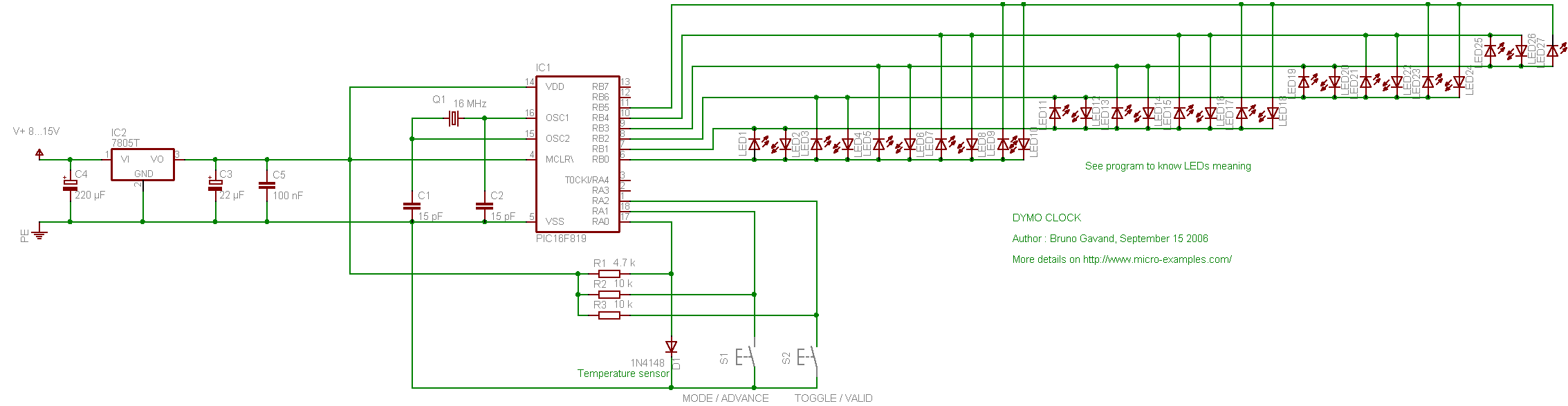
The following circuit illustrates the PIC16F819 Dymoclock Sensor Circuit Diagram. Features include an economical temperature sensor, the use of only LEDs, and the absence of a decoder. The PIC16F819 Dymoclock Sensor Circuit utilizes a PIC16F819 microcontroller, which is a versatile...
For several years, a rear fog lamp has been mandatory for trailers and caravans to enhance visibility in foggy conditions. When the fog lamp is activated, the fog lamp of the towing vehicle must be turned off to prevent...
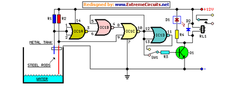
This circuit utilizes a relay to control a water pump for automatic level regulation of a water reservoir or well. The shorter steel rod acts as a high water sensor, while the longer rod serves as a low water...
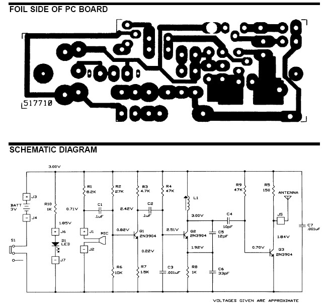
The frequency range for the FM transmission band is 90 MHz (megahertz, or 90 million cycles per second). Due to the variable tuned circuit in the FM transmitter, it can be tuned to a specific frequency within the local...
This audio meter can be monitored using a small panel meter with a circuit constructed from discrete components. The audio level meter circuit exhibits a flat frequency response ranging from approximately 20Hz to over 50kHz. The input sensitivity is...
Crime in general is still on the rise, and having a security alarm installed is no longer a prerequisite of the wealthy. Here is a simple and compact security solution. A compact security alarm system can be designed to enhance...