
fm transmitter

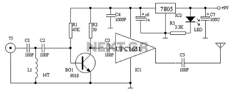
The circuit design incorporates a microphone with a specific output impedance, which is critical for ensuring optimal performance and signal integrity. The original schematic specifies a resistor value of 68k ohms, which is typically chosen to match the characteristics of certain microphones. However, in this implementation, a microphone with a lower output impedance of 1.5k ohms was selected. This necessitates the use of a 1.5k resistor to maintain proper impedance matching within the circuit.
Impedance matching is crucial in audio applications to minimize reflections and maximize power transfer between the microphone and subsequent stages of the circuit, such as amplifiers or signal processors. The choice of a 1.5k resistor in place of the 68k ensures that the microphone's output is effectively coupled to the input of the following stage, providing a balanced and clear audio signal.
In addition to the resistor, the schematic may include other components such as capacitors for AC coupling and power supply decoupling, which further enhance the performance of the microphone circuit. Proper layout and grounding techniques should also be considered to reduce noise and interference, ensuring high-quality audio capture.The first resistor on the left in the schematic says 68k. This will vary depending the the microphone. In our case we used a microphone from digikey with a 1. 5k output impedance, so we matched it with a 1. 5k resistor instead of using a 68k. 🔗 External reference
Related Circuits
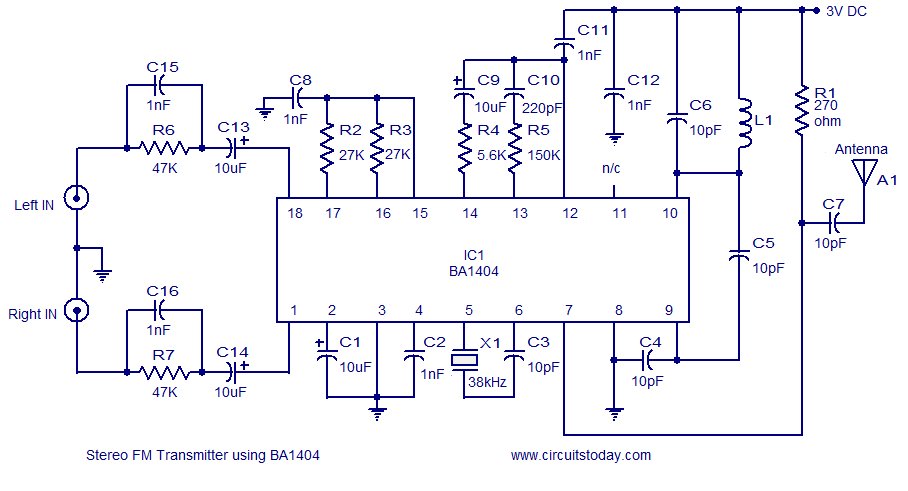
A simple and high-quality FM transmitter circuit designed based on the BA1404 IC. This FM transmitter circuit can be operated from a 3 V battery. The FM transmitter circuit utilizing the BA1404 integrated circuit (IC) is engineered for simplicity and...
Circuit Overview Many families now own various electronic devices such as televisions, VCD players, video recorders, game consoles, cameras, and DVDs. This circuit involves an RF signal repeater designed to work with a television signal transmitter, covering a radius...
This article addresses inquiries regarding a low-power FM transmitter designed to accept input from various sound sources, such as a guitar or microphone, and transmit on the commercial FM band. It is important to select an unused frequency on...

The circuit diagram of an AM transmitter circuit based on three transistors. With correct tuning and a matching antenna, the transmitter can effectively transmit amplitude-modulated signals. The AM transmitter circuit utilizes three transistors configured to amplify and modulate the input...
This compact transmitter is suitable for less demanding Doppler propagation measurements. It is designed for operation on the 80m band but can be easily adapted for the 40m or 20m bands. The output power is approximately 500mW of unmodulated...

This is a basic telephone broadcaster or transmitter designed for eavesdropping on telephone conversations. The circuit can also function as a wireless telephone amplifier. A key feature of this phone transmitter is that it derives its power directly from...