
A brushless DC motor road
A comprehensive electronic schematic for the described water magnet activation system involves several critical components and their interconnections. The stator coil is segmented into four distinct groups, each comprising multiple turns of wire wound around a magnetic core. These groups are connected to a control unit that generates pulse signals. The control unit typically consists of a microcontroller or a dedicated pulse-width modulation (PWM) circuit that ensures precise timing and phase control.
The pulse signals from the control unit are fed to a series of switching devices, such as MOSFETs or transistors, which act as electronic switches to alternate the current through each coil group. This switching creates a rotating magnetic field necessary for the operation of the water magnet. The timing of the switches is crucial and must be synchronized to achieve the desired phase difference of 180 degrees between adjacent coil groups.
Incorporating feedback mechanisms can enhance the system's performance. For example, the LEDs serve as visual indicators of the operational status and phase alignment. The light emitted from the LEDs can be used to provide real-time feedback on the coil activation, which can be monitored for efficiency and troubleshooting.
The use of high-frequency low-power germanium transistors, such as the 13AG12, is essential for minimizing power loss while maintaining effective switching capabilities. These transistors should be configured in a manner that allows for rapid switching, thereby ensuring a smooth and continuous rotation of the magnetic field.
The inclusion of red light-emitting diodes in the circuit not only provides visual feedback but also can be part of a more extensive control system that includes sensors to detect the position of the rotor. This can lead to more sophisticated control algorithms that adapt the coil activation based on real-time conditions.
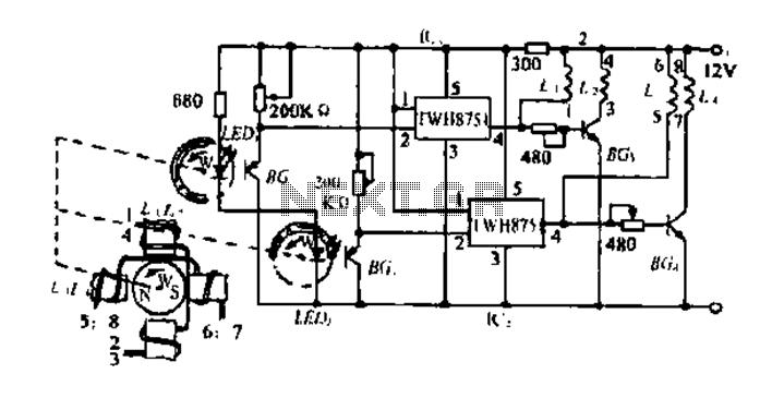
Overall, the design must account for thermal management, component ratings, and the overall efficiency of the system to ensure reliable operation over extended periods. This comprehensive approach will allow for the successful implementation of the water magnet activation system as described.F to turn a water magnet, the stator coil into 4 groups. 4 stars all set of coils through mediums P pulse signals by the rotor control number, so as to form a rotating magnetic field that the rotary f operation. BG. Wherever feel meters from LEDi the signal to control lc ,. BG Bu Bu so that each guide, cut lL (or off, saturated conduction) makes Ll/2 out of phase I80. Similarly, Si, L4 of phase 1800, and the phase changes Lm LED, the light from the phase difference signal 45. Press as l cut set four groups of coils can be formed by the digging of a rotor system rotating magnetic field (not dead).
BG, B Island germanium high -frequency low-power three-arm pull as 13AG12. Will top off the old file can be used. T.ED, t.EDz use of red light-emitting diode - BGi BG4 silicon power granted i hip (see motor power depending}, Ll, L2, k, l were collected Hj double wound law intended to depression. : experimental power domain circuit clamor enough people.
Related Circuits
The first pulse motor that is used to position control. Features were incorporated for positioning control. This does not mean intelligent and autonomous driving the motor in response to movement commands from the host. The key to controlling the...
This 3A charger was originally designed to work with small batteries like those used in motorcycles. In principle it can be used to charge car batteries also but will take a lot longer. The charger below charges a battery...
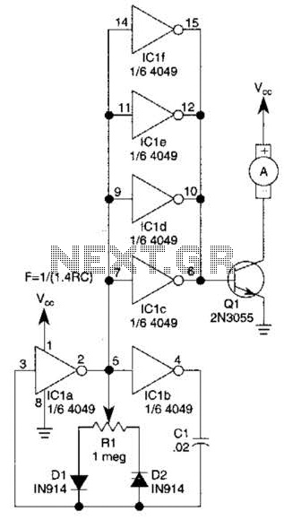
This circuit will drive a small DC motor over a wide range of speeds without stalling by controlling the duty cycle of the motor, rather than the supply voltage. The described circuit utilizes pulse width modulation (PWM) to effectively control...
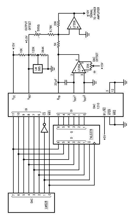
The LM628 and LM629 dedicated motion-control processors can be utilized to design various applications involving DC and brushless DC servo motors, as well as other servomechanisms. The power path of this electronic project, which functions as a motor driver,...
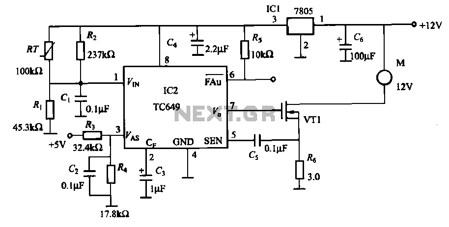
A motor is a heating device that can overheat, often due to accidents or overloads caused by excessive coil winding temperatures. The TC649 motor overheating protection and drive circuit, depicted in FIG. 1-9, utilizes an NTC thermistor (RT) positioned...
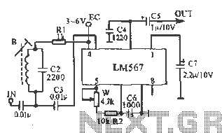
This figure illustrates the schematic of the LM567 SCA broadcast reception information machine. The LM567 serves as a narrow-band phase-locked loop designed primarily for SCA broadcast demodulation. The configuration includes a potentiometer (W) and capacitor (C6) that determine the...