
FM Transmitter circuit

To implement the change from an electret microphone to a 3.5" audio jack, the following modifications should be considered. The electret microphone typically has two terminals: one for the audio signal and the other for power. The audio jack will require a similar configuration, where the tip of the jack carries the audio signal, and the sleeve provides a ground connection. It is essential to identify the corresponding pins on the audio jack to ensure proper connectivity.
1. **Wiring the Audio Jack**: The audio jack can be connected in place of the microphone. The signal pin from the microphone should be connected to the tip of the audio jack, while the ground pin should connect to the sleeve. If the original circuit includes any biasing resistors for the microphone, these may need to be adjusted or removed, as the audio jack will not require the same biasing.
2. **Adjusting Component Values**: Depending on the circuit design, it may be necessary to adjust component values such as resistors and capacitors that were tuned for the microphone's characteristics. The input impedance of the audio jack may differ, so it is advisable to test the circuit after modifications to ensure optimal performance.
3. **Incorporating a Battery Indicator LED**: To add a white LED for battery status indication, it is recommended to connect the LED in parallel with the battery. A current-limiting resistor should be included in series with the LED to prevent excessive current draw, which could damage the LED. The resistor value can be calculated using Ohm's law, taking into account the forward voltage drop of the LED and the supply voltage. For a 3V battery, a resistor value of approximately 150 to 330 ohms is typically suitable, but this may vary based on the specific LED used.
In conclusion, replacing the electret microphone with a 3.5" audio jack involves careful wiring and potential adjustments to circuit components to ensure compatibility. Additionally, integrating a battery status LED will provide a visual indication of battery health, enhancing the functionality of the circuit. Testing the circuit after modifications is crucial to verify that both audio transmission and battery indication operate as intended.I wanted to use a 3. 5" jack instead of a microphone, I would need to change something else in the circuit. What would be changed in order to use an audio jack instead of a electret microphone to transmit One like this: taken from an old radio. It has 7 pins, four small knobs on one side, and a bigger one on the other side. It does not have any model number. One more thing, I hope it doesn`t bother you: Where in the circuit could I add a white LED so I know the battery isn`t dead I think it`s 3V, but maybe it`s more, since it doesn`t look very bright on a cell battery. 🔗 External reference
Related Circuits

A simple technique for measuring frequencies across a wide range with acceptable accuracy limits using a PC is presented. This method follows the basic principle of measuring low frequencies, where the period of a complete wave is measured and...

The circuit diagram illustrates a dual radio remote control switch system. The transmitter section features Q3, which generates a high-frequency carrier signal, while Q1 and Q2 form the oscillator circuit. Pressing switch SW1 results in an oscillation frequency of...

This simple-to-construct water fishing thermometer circuit is intended for use in sports applications, such as fishing contests. A sensor measures... This water fishing thermometer circuit is designed to provide accurate temperature readings of water, making it an essential tool for...
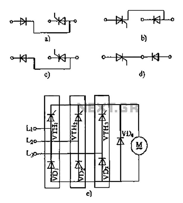
The thyristor linking arm rectifier module is a three-phase half-controlled bridge rectifier circuit. The thyristor-rectifier module linking arm consists of a thyristor and a rectifier diode connected in series or parallel, designed to fulfill specific requirements in power circuits....

The gate N1 serves as a buffer to amplify the signals from the condenser microphone. The inverter N2, along with its associated components, creates a radio frequency oscillator operating in the FM range. The varicap diode BB109 is utilized...
The circuit operates by using a clock signal to drive four D-flip-flops in the control section, which store the on/off state of each current direction for the two stepper motor coils. The flip-flops create a finite state machine (FSM)...