
WSl57 + 5V 1.6A precision switching power supply circuit comprising

The circuit functions by integrating an optical coupler, specifically the CNY75A, which facilitates isolation between the input and output stages while allowing signal transfer. The TL431 serves as a precision shunt regulator, maintaining a stable reference voltage of 2.5V. The resistors R3, R4, and R5 are employed to limit current through the sampling resistor, ensuring that the circuit operates within safe parameters.
As the output voltage (Uo) fluctuates, it impacts the voltage across the sampling resistor, which is monitored against the TL431’s internal reference. This feedback mechanism is crucial for maintaining the desired output characteristics. The changes in voltage affect the K side potential, leading to variations in the LED operating current within the CNY75A. Consequently, this modulation alters the luminous intensity of the LED, which acts as an input signal for the optocoupler.
The optocoupler's output is then used to adjust the control current flowing to the WS157, allowing for precise manipulation of the duty cycle. Such fine-tuning is essential for achieving the desired regulation in applications where stability and accuracy are paramount. The inclusion of the CNY75A not only allows for effective signal transfer but also ensures electrical isolation, which is critical in protecting sensitive components from potential voltage spikes or noise.
The switches SV and SI are configured to provide specific tolerance levels, ensuring that the circuit operates reliably under varying conditions. The power tolerance of 0.1% for switch SV and 0.78% for switch SI reflects the precision required in this circuit design, highlighting the importance of maintaining accuracy in the control and regulation processes. Overall, this circuit design exemplifies the integration of optical coupling and precision regulation to achieve effective and reliable performance in electronic applications. As shown, the circuit adds an optical coupler (CNY75A) and adjustable precision shunt regulator (TL431). Current limiting resistor R3, R4 and R5 for the sampling resistor. When Uo changes, the voltage on the sampling and TL431 internal 2.5V reference voltage, K side potential changes, changes CNY75A the launch tube (LED) operating current and luminous intensity, and then through the optocoupler to adjust the control WSl57 side current, duty cycle can be finely adjusted to achieve precise purpose of regulation. CNY75A electrical isolation also play a role. Found this switch Sv 0.1% power, SI 0.78%.
Related Circuits
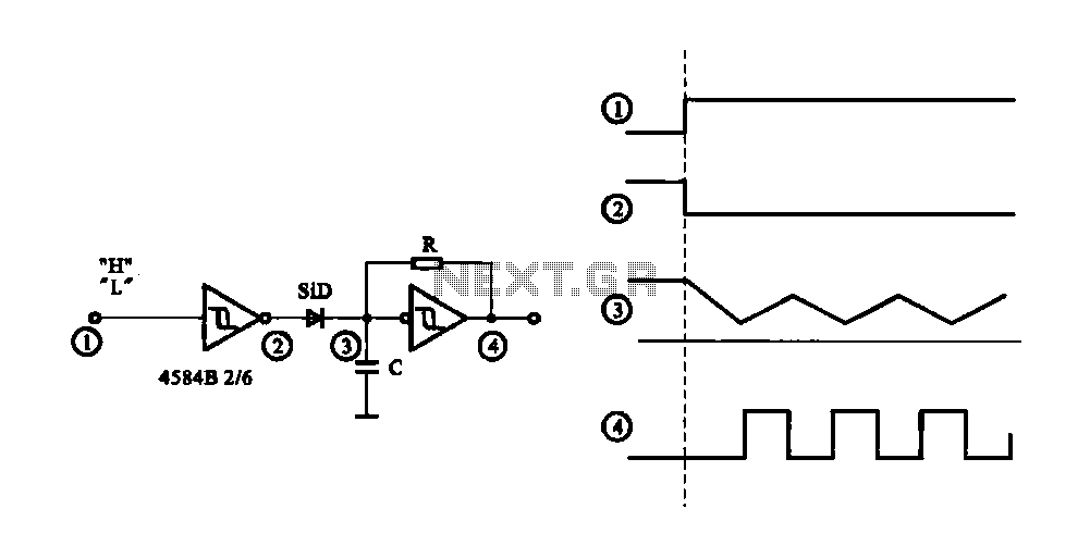
The circuit generates a controlled pulse signal. When a high pulse signal is applied to the input terminal O (start), the output pulse signal is activated. Conversely, when a low signal is received at the input terminal O (stop),...
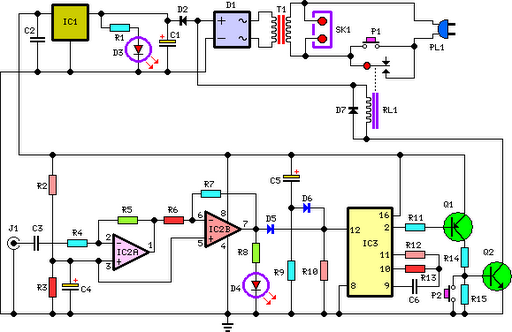
This circuit deactivates an amplifier or any connected device when a low-level audio signal at its input is absent for at least 15 minutes. Pressing P1 turns the device on, supplying power to any appliance connected to SK1. The...
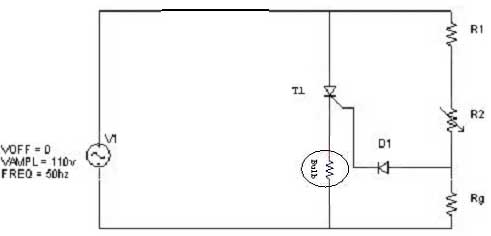
Simple resistor and diode combinations are used to trigger and control silicon-controlled rectifiers (SCRs) across the full 180-degree electrical range, exhibiting reliable performance at commercial temperatures. These circuits function optimally when SCRs possess relatively high gate sensitivities. In this...
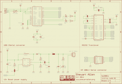
A personal digital assistant was introduced in 1994, often referred to as a palmtop computer. It was notable for being, with minor exceptions, an MS-DOS-compatible computer in a palmtop format. It featured a monochrome graphic display, a QWERTY keyboard,...
Here is a circuit diagram for adjusting the brightness of a light bulb. The second battery is utilized to power the circuit. This circuit can be used to modify the brightness of images during close-up photography with a digital...
.png)
Have you ever considered implementing your own home security alarm system? It is one of the simplest and most interesting circuits for electronics beginners. The new home security equipment utilizes a Light Dependent Resistor (LDR) to detect security breaches....