
X-Rays with Receiving Tubes
The cold cathode tube went out of use shortly after 1910 when W. D. Coolidge introduced a tube with a hot cathode (thermionic) electron emitter. The Coolidge tube, which uses high vacuum (typically below 10-5 Torr), has a number of advantages over the gas tube.
With the gas tube, the electron current, at a given voltage, is dependent on the voltage across the tube which, in turn, can vary depending upon the degree of vacuum. Furthermore, the degree of vacuum will change over time. This will affect the spectrum (hence the penetrating quality) of the x-ray output as well as the intensity. With a heated cathode in a high vacuum tube, the electron current may be controlled simply by varying the filament temperature. Then, by varying the voltage across the tube, the penetrating power of the x-rays (a function of the x-ray energy) may be varied. Thus, two important parameters may be controlled independently. Bob Templeman has been able to use conventional vacuum tubes as cold cathode x-ray tubes. He has done most of his work with the 6BK4B, a beam triode used for voltage regulation of high voltage, low current dc power supplies in color and black-and-white television sets. The tube has an octal base and a plate cap. Bob has also tried several other tubes including the 6EN4 (which is very similar to the 6BK4B), 3AT2, 3CZ3A, and 3BW4. He has found that all will emit measurable amounts of x-radiation but only the beam tubes appear to provide sufficient radiation to expose standard films.
Since the tube is operated in a cold cathode mode, the tube’s degree of vacuum is quite important. Bob found that about one in eight tubes is able to produce enough radiation to expose his film. One might ask why not just heat the filament to get an assured, controlled emission of x-rays? The answer lies in the basic characteristics of a high vacuum diode. A ‘normal’ hot cathode vacuum diode, such as a rectifier tube, operates in a region where the tube current varies nearly linearly with the voltage drop. Thus, substantial increases in current would be required to produce a voltage drop across the tube significant enough to produce useful levels of x-rays. For normal tubes, the current would be well in excess of the tube's power rating. Normal operation for a rectifier tube is moderate to high current with a low voltage drop.
What is good for rectifiers is not good for x-ray tubes. In the case of the x-ray tube, the tube is operated in the upper part of the characteristic curve, the ‘saturation’ region. In this mode, the voltage can be increased with little increase of electron current. Getting the right balance between current and voltage is part of each tube's design. Also, as noted before, varying the filament temperature (e.g. by means of varying the filament voltage) allows the intensity of the tube’s output to be adjusted. For each filament temperature, there is a different current vs. voltage characteristic.
The High Voltage Power Supply
Bob uses a TV flyback driven voltage multiplier to power his tubes. This is a fairly common implementation using a pair of general purpose NPN transistors to drive a 10 turn primary which is added to a stock flyback.
The multiplier is of the cascade (Cockcroft-Walton) type. A modular tripler scavenged from a TV set can be used as these can usually be pushed to about 40 kV without failing. A better alternative is to make the multiplier from scratch using discrete diodes and ceramic disk capacitors. The diodes should be rated at 20 kV. A good value for the capacitors would be 0.001 uF at 15 kV.
As the flyback circuit will provide about 10 kV into the multiplier, six stages are required to boost the voltage to a maximum of 60 kV. The multiplier can be assembled on a piece of bare perf board with good separation between the components. To avoid excessive leakage or arcing, immerse the whole multiplier assembly in mineral oil. A rectangular plastic food storage dish makes a good container for this assembly.
A means of measuring the high voltage output is essential. A resistive divider is appropriate for this application. However, standard components are not suitable for high voltages, low current measurements. A good circuit for measuring the output voltage is a potted TV focus divider (RCA SK series or equivalent) which contains the necessary high voltage/high value resistors. The only additional components needed are one external resistor and a standard high impedance dc meter.
When testing the completed multiplier, avoid the temptation to draw sparks from the output. This will only stress the components and lead to premature failure.
The operating regions of hot cathode rectifiers and x-ray tubes are shown in Figure 1.
The described circuit utilizes old TV tubes repurposed as cold cathode x-ray emitters, specifically the 6BK4B and similar types, to generate x-rays for imaging applications. The cold cathode operation relies on maintaining a soft vacuum within the tube to allow for effective electron flow. The voltage multiplier circuit, based on the Cockcroft-Walton design, efficiently steps up the voltage supplied by a flyback transformer to levels suitable for x-ray generation. The careful selection of components, including high-voltage rated diodes and capacitors, ensures reliability and safety during operation. The assembly of the multiplier on a perf board, along with immersion in mineral oil, mitigates the risk of arcing and leakage, which is critical in high-voltage applications. The use of a resistive voltage divider for measurement purposes is essential for monitoring the output, ensuring that the x-ray generation remains within safe and effective parameters.Old TV tubes are used as cold cathode x-ray emitters in a simple apparatus developed by Bob Templeman of Chicago, Illinois. With selected beam power tubes of the type used in the high voltage section of TV receivers, the intensity is adequate to make x-rays photographs of objects using standard films.
The earliest x-ray tubes were of the cold cathode variety. These tubes, referred to as Crookes or Hittorf tubes, were of the general class of gas tubes since the pressure had to be in the ‘soft’ vacuum range (about 10-3 to 10-4 Torr) to permit the passage of electrons from the cathode to the x-ray producing target in a so-called ‘dark’ discharge. Higher pressures would result in a luminous discharge (as in a neon lamp) with only a small potential drop across the tube. Lower pressures (a 'hard' vacuum) would result in no current flow regardless of applied voltage. The cold cathode tube went out of use shortly after 1910 when W. D. Coolidge introduced a tube with a hot cathode (thermionic) electron emitter. The Coolidge tube, which uses high vacuum (typically below 10-5 Torr), has a number of advantages over the gas tube.
With the gas tube, the electron current, at a given voltage, is dependent the voltage across the tube which, in turn, can vary depending upon the degree of vacuum. Furthermore, the degree of vacuum will change over time. This will affect the spectrum (hence the penetrating quality) of the x-ray output as well as the intensity.
With a heated cathode in a high vacuum tube, the electron current may be controlled simply by varying the filament temperature. Then, by varying the voltage across the tube, the penetrating power of the x-rays (a function of the x-ray energy) may be varied.
Thus, two important parameters may be controlled independently. Bob Templeman has been able to use conventional vacuum tubes as cold cathode x-ray tubes. He has done most of his work with the 6BK4B, a beam triode used for voltage regulation of high voltage, low current dc power supplies in color and black-and-white television sets. The tube has an octal base and a plate cap. Bob has also tried several other tubes including the 6EN4 (which is very similar to the 6BK4B), 3AT2, 3CZ3A, and 3BW4.
He has found that all will emit measurable amounts of x-radiation but only the beam tubes appear to provide sufficient radiation to expose standard films. Since the tube is operated in a cold cathode mode, the tube’s degree of vacuum is quite important. Bob found that about one in eight tubes is able to produce enough radiation to expose his film. One might ask why not just heat the filament to get an assured, controlled emission of x-rays?” The answer lies in the basic characteristics of a high vacuum diode.
A ‘normal’ hot cathode vacuum diode, such as a rectifier tube, operates in a region where the tube current varies nearly linearly with the voltage drop. Thus, substantial increases in current would be required to produce a voltage drop across the tube significant enough to produce useful levels of x-rays.
For normal tubes, the current would be well in excess of the tube's power rating. Normal operation for a rectifier tube is moderate to high current with a low voltage drop. What is good for rectifiers is not good for x-ray tubes. In the case of the x-ray tube, the tube is operated in the upper part of the characteristic curve, the ‘saturation’ region. In this mode, the voltage can be increased with little increase of electron current. Getting the right balance between current and voltage is part of each tube's design. Also, as noted before, varying the filament temperature (e.g. by means of varying the filament voltage) allows the intensity of the tube’s output to be adjusted. For each filament temperature, there is a different current vs. voltage characteristic. The High Voltage Power Supply Bob uses a TV flyback driven voltage multiplier to power his tubes. This is a fairly common implementation using a pair of general purpose NPN transistors to drive a 10 turn primary which is added to a stock flyback.
The multiplier is of the cascade (Cockcroft-Walton) type. A modular tripler scavenged from a TV set can be used as these can usually be pushed to about 40 kV without failing. A better alternative is to make the multiplier from scratch using discrete diodes and ceramic disk capacitors.
The diodes should be rated at 20 kV. A good value for the capacitors would be 0.001 uF at 15 kV. As the flyback circuit will provide about 10 kV into the multiplier, six stages are required to boost the voltage to a maximum of 60 kV. The multiplier can be assembled on a piece of bare perf board with good separation between the components.
To avoid excessive leakage or arcing, immerse the whole multiplier assembly in mineral oil. A rectangular plastic food storage dish makes a good container for this assembly. A means of measuring the high voltage output is essential. A resistive divider is appropriate for this application. However, standard components are not suitable for high voltages, low current measurements. A good circuit for measuring the output voltage is a potted TV focus divider (RCA SK series or equivalent) which contains the necessary high voltage/high value resistors. The only additional components needed are one external resistor and a standard high impedance dc meter.
When testing the completed multiplier, avoid the temptation to draw sparks from the output. This will only stress the components and lead to premature failure. The operating regions of hot cathode rectifiers and x-ray tubes are shown in Figure 1. 🔗 External reference
Related Circuits
Nixie tubes were utilized for numeric and occasionally alphanumeric displays prior to the advent of LEDs and LCDs. They resembled light bulbs more than traditional tubes, yet were encased in evacuated glass shells akin to vacuum tubes and featured...
The preamplifier is straightforward, utilizing a low-noise integrated circuit manufactured by Hewlett Packard, specifically the MGA86563. This device features a noise figure of approximately 2 dB and operates within a frequency range of 0.5 GHz to at least 6...
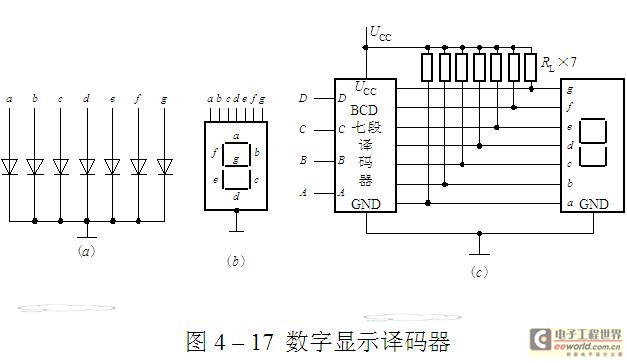
The luminescent diode (LED) is constructed from gallium arsenide (GaAs), a specialized semiconductor material, and gallium arsenide phosphide. It can be used individually or assembled into segment-type or lattice LED display devices. The display unit consists of a sectional...
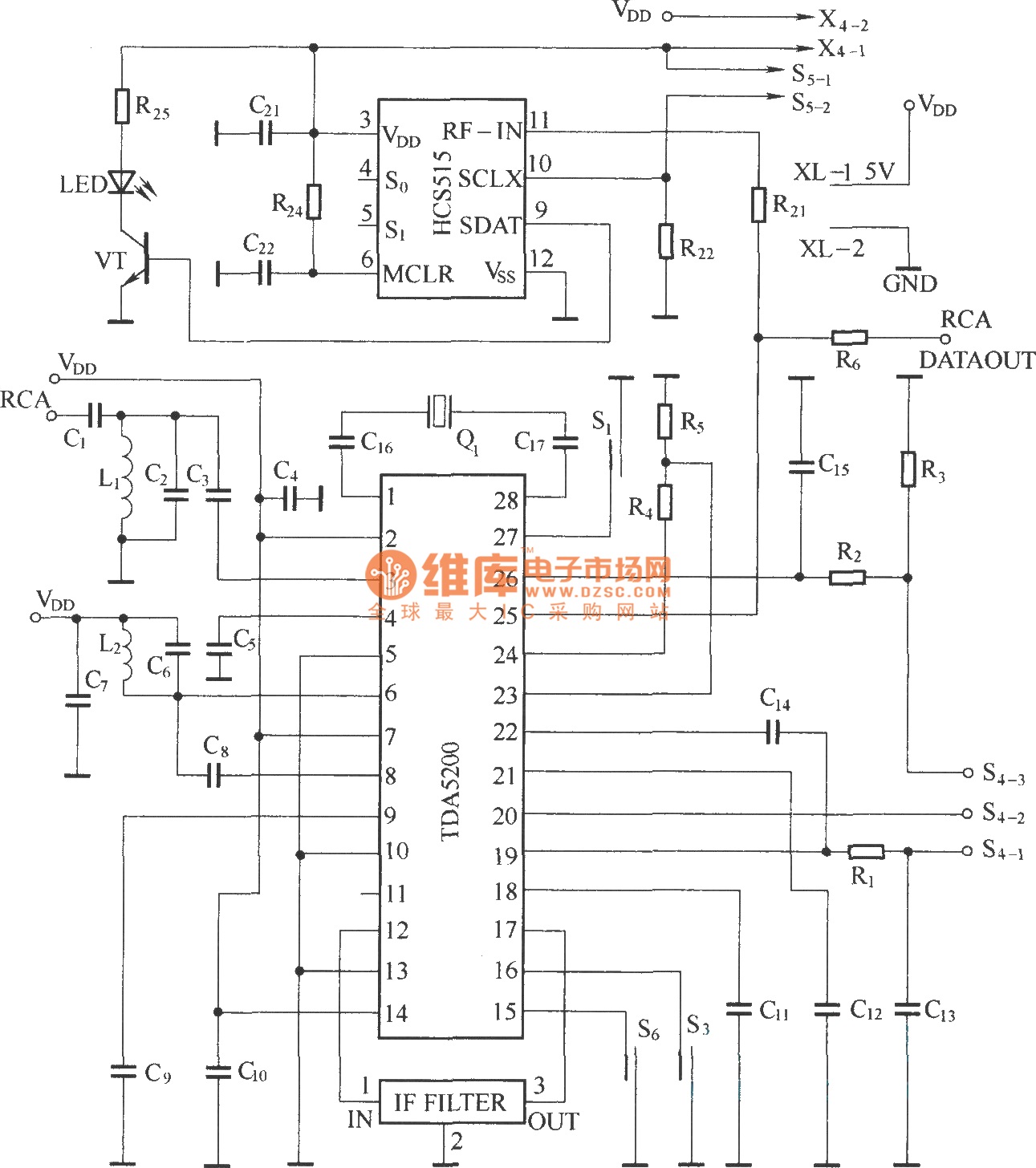
The TDA5200 is a low-power, single-chip ASK superheterodyne receiver circuit. It operates within two frequency blocks: 868 to 870 MHz and 433 to 435 MHz. This circuit is highly integrated, requiring minimal external components while offering excellent functionality. It...
A discussion of the Williamson Amplifier should first include an overview of its context in the evolution of the vacuum tube and its application to high-fidelity audio reproduction. Transformer coupling was widely used before the war due to its...
A NIXIE tube was mounted on a wooden cigar box, with the anode connected through a large series resistor to the live wire of a 220V mains supply. Touching one of the cathodes caused the numbers to glow, sparking...