
Xenon Flasher

The transistor oscillator in this project is a type of blocking oscillator, also referred to as a pulsed, feedback, or flyback oscillator. The high voltage produced by the secondary winding occurs when the transistor is switched off, causing the magnetic flux to collapse and generate high voltage in the secondary (or tertiary) winding. The oscillator converts a 1.5V DC supply voltage into a 350V AC waveform, which is then rectified by a high-speed diode to charge the 120µF, 330V electrolytic capacitor.
For the oscillator to function, positive feedback is required, which encourages the transistor to continue in its current operational direction. This feedback is similar to motivating a cyclist to pedal harder, whether uphill or downhill. A 220Ω resistor connected to the base of the transistor allows a small amount of current to flow through it and the primary winding, generating magnetic flux. It is crucial to understand that this is expanding flux, meaning the magnetic field is strengthening. This flux passes through the transformer’s windings, producing voltage and current in each turn.
The transformer consists of three separate windings. The feedback winding connects between the 220Ω resistor and the transistor's base. As the transistor turns on, the voltage generated in the feedback winding adds to the voltage from the resistor, further enhancing the transistor's conduction. This process continues until the magnetic flux reaches its maximum, transitioning to stationary flux, which does not produce voltage or current in the other windings. Consequently, the feedback current ceases, causing the transistor to turn off slightly, reducing the magnetic flux, which then enters a collapsing state. This collapsing magnetic flux cuts through the transformer turns, inducing voltage in the secondary windings.
The described circuit demonstrates the principles of high-voltage generation and the operation of feedback oscillators, providing valuable hands-on experience with electrical safety and high-voltage components.This project generates 350V DC and stores the voltage in a large electrolytic. This voltage will not kill you, but will deliver a nasty SHOCK! For this reason, the project has a great benefit. It will teach you to work very carefully on equipment with high voltages and if you do get a shock, you will appreciate electricity EVEN MORE! Simply discha rge the 120u electrolytic with a screwdriver or jumper lead before working on the circuit. I do. I`m not silly. I don`t want to get a bite or tingle each time I pick up or work on the board. There is no reason why beginners cannot experience working on this project as it contains non-lethal high voltages and is a very good grounding for electrical safety. We forgot to mention the other high voltage produced by the circuit. As you will learn in the notes, a trigger transformer is also included in the circuit and it produces a very high voltage to trigger the Xenon tube to produce a flash.
This trigger voltage is approx 2, 000 volts but since it is only present for a very short period of time, you would have to be holding the circuit at the instant when a flash occurs, to feel the spike. None the less, this 2kV is part of the circuit and adds to the fact that this project is packed with features.
We start the discussion with the transistor oscillator. It`s not really a sinewave oscillator as this infers the output is a nice, clean sinewave. It`s really a blocking oscillator or pulsed oscillator or feedback oscillator or flyback oscillator as the high voltage produced by the secondary winding occurs when the transistor is switched off and the magnetic flux collapses and creates the high voltage in the secondary (also called the tertiary or "overwind") winding. For more details on the operation of this type of oscillator, see our project: The oscillator converts the 1.
5v DC supply voltage to a 350v AC waveform. This waveform is rectified by a high-speed diode and charges a 120u 330v electrolytic. For an oscillator to work, it must have positive feedback. In other words, positive feedback is a signal that encourages the transistor to keep moving in the direction it is travelling. This can be in the "turning-on" direction or the "turning-off" direction. It`s a bit like encouraging a cyclist to peddle harder up hill. That`s positive feedback. Then to encourage him to peddle harder down-hill. That`s also positive feedback. The transistor gets turned on a small amount by the 220R resistor on the base. Current flows through the transistor and also the winding connected to the collector. This is called the primary winding. The primary winding produces magnetic flux and the important thing to remember is the flux is EXPANDING FLUX.
In other words the flux is getting stronger (or more-accurately: MORE LINES OF FLUX ARE BEING PRODUCED - THE FLUX-LINES ARE CLOSER TOGETHER). This flux passes through all the turns on the transformer and a voltage (and current) is produced in each turn.
There are three separate windings on the transformer, (we really say the current is available as a current cannot be measured until is it actually flowing): The feedback winding is connected between the 220R resistor and the base of the transistor. When the transistor turns on, the voltage produced in the feedback winding ADDS to the voltage supplied by the resistor and this turns the transistor on MORE.
The transistor keeps turning on HARDER until it cannot turn on any more. The flux in the transformer is a maximum but it is not EXPANDING FLUX. It is called STATIONARY FLUX. Stationary flux does not produce a voltage or current in the other windings and thus the voltage and current produced in the feedback winding ceases to flow. This causes the transistor to turn off a small amount and the magnetic flux in the transformer is REDUCED.
This flux is now called COLLAPSING MAGNETIC FLUX and it cuts the turns in the transformer and the voltage it produces in th 🔗 External reference
Related Circuits
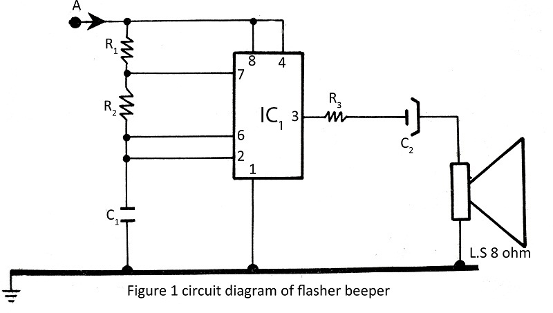
A flasher with a beeper is very easy to build and assemble. The flasher with a beeper is constructed using very common components, with various projects utilizing the NE555 timer IC. The flasher circuit typically employs the NE555 timer IC...
The 8-lead plastic mini-DIP LM3909 integrated circuit was developed by National Semiconductor in the mid-1970s. It is a monolithic oscillator specifically designed to flash Light Emitting Diodes (LEDs). By utilizing the timing capacitor for voltage boosting, it can deliver...
An LED flasher circuit can be constructed using a 555 integrated circuit (IC). The use of the 555 IC allows for greater flexibility in adjusting the flashing rate of the LED. This LED flasher circuit is similar to other...
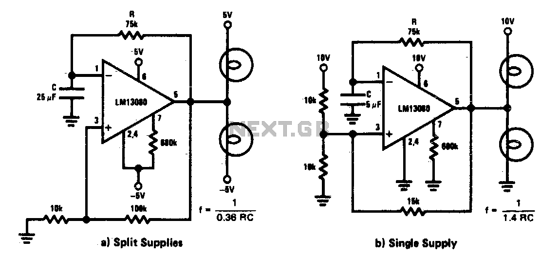
This circuit functions as a low-frequency warning device. The output from the oscillator generates a square wave signal, which is utilized to operate lamps or small relays. The circuit alternately flashes two incandescent lamps. The low-frequency warning device circuit typically...
The 555 circuit below is a flashing bicycle light powered with three C or D cells (4.5 volts). The two flashlight lamps will alternately flash at an approximate 1.5 second cycle rate. Using a 4.7K resistor for R1 and...
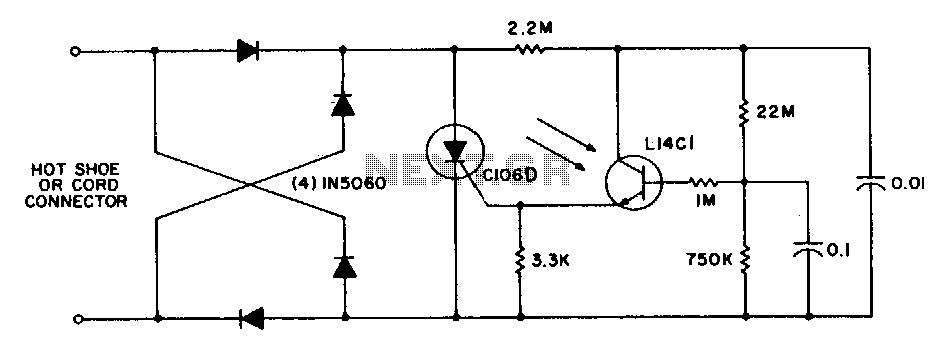
This circuit is utilized for remote photographic flash units that synchronize with the flash attached to the camera. It is designed to connect to the trigger cord or hot shoe of a commercial portable flash unit, allowing the unit...