
XOR GATE UP DOWN COUNTER

The 7493 binary counter is a versatile component in digital electronics, capable of counting in both ascending and descending order. By incorporating the 7486 XOR gates, the counter can be configured to switch its counting mode based on the state of the DN/UP control line. This flexibility allows for dynamic counting applications where the direction of count may need to be altered based on external conditions.
In the up-count mode, the counter increments its value with each clock pulse applied to the AIN input, while the QA output reflects the least significant bit of the count. When the DN/UP line is asserted low, the counting sequence proceeds from 0 to 15. Conversely, in the down-count mode, when the DN/UP line is high, the counter decrements its value, starting from 15 and counting down to 0.
The reset functionality of the counter is critical for initializing the counting sequence. When the reset input is held high, it not only inhibits the counting operation but also ensures that the outputs are set to a predefined state, either 0 or 15, depending on the counting direction. This reset capability is essential for applications requiring precise control over the counting process.
Cascading multiple 7493 counters enhances the counting range and allows for more complex counting applications. By connecting the QD output of one counter to the clock input of another, a multi-stage counting system can be created, enabling counts beyond the inherent limit of a single counter. This cascading approach is particularly useful in applications such as digital clocks, frequency counters, and event counters, where extended counting capabilities are necessary.
Overall, the combination of the 7493 binary counter and the 7486 XOR gates offers a powerful solution for applications requiring flexible counting mechanisms, with the ability to easily reset and cascade for extended functionality.One can transform an ordinary binary counter, such as a 7493, into an up/down counter with mode control by adding XOR gates 7486 to the counter`s outputs. The circuit counts up when the DN/UP line is low and down when the DN/UP line is high. To use the 7493 counter to count out its maximum count length of 0 - 15, connect the QA output to the BIN i
nput and apply clock pulses to the AIN input. The reset input, when high, inhibits the count inputs and simultaneously retums the outputs AO through DO to low in the up-count mode or 15 in the down-count mode. For normal counting, the reset input must be low. 0ne can easily cascade this counter by feeding the QD line to the clock input of a succeeding counter.
🔗 External reference
Related Circuits
The objective is to enhance information transmission through the distribution of articles. Please contact us via email at [email protected] within 15 days if there are any issues related to article content, copyright, or other concerns. Prompt deletion will occur...
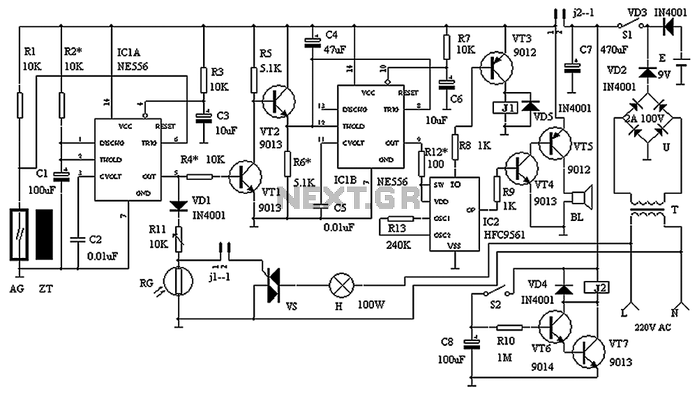
The circuit consists of a triggering device, a monostable delay circuit, an alarm sound generator, an audio amplifier circuit, and a light control circuit, with a partially blocking preset circuit and power circuit. When the door is locked and...
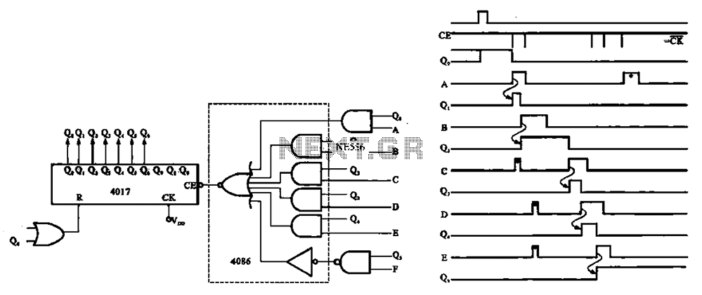
An asynchronous counter is illustrated in this circuit. It operates without a clock synchronization signal, making it suitable for use in a random counter or as an independent unit circuit. An asynchronous counter, also known as a ripple counter, is...
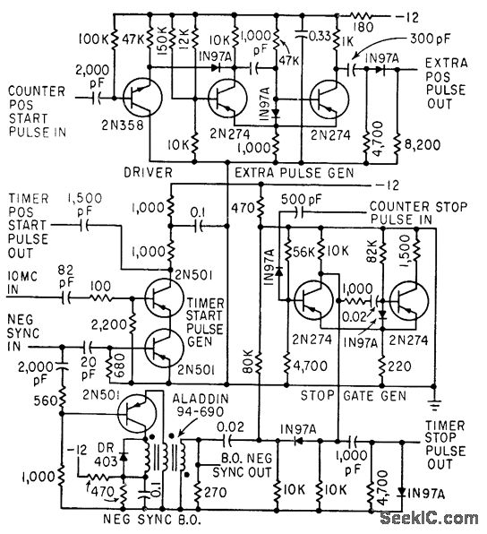
The timer start-pulse generator is a fast series-transistor coincidence circuit. The slope-gate generator is a one-shot multivibrator that prevents the 1N97A diode from passing the blocking oscillator's negative sync pulse until the multivibrator fires. This circuit is utilized to...
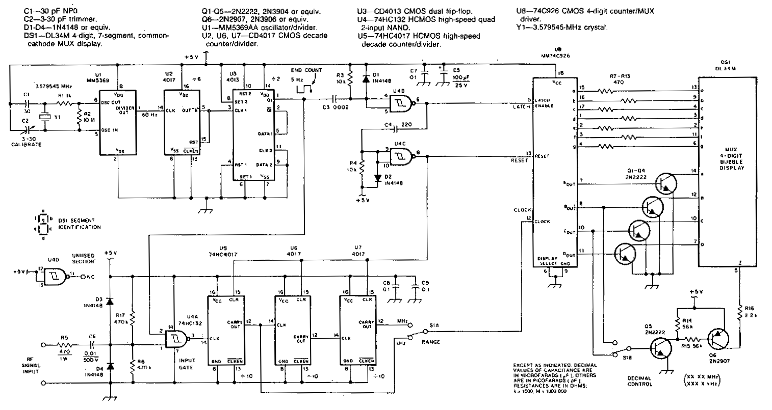
This counter features a four-digit display that can be switched to display frequencies ranging from 1 to 40 MHz, with a resolution of 100 Hz. The MM74C926 CMOS IC serves as the four-digit decimal counter, which can latch a...
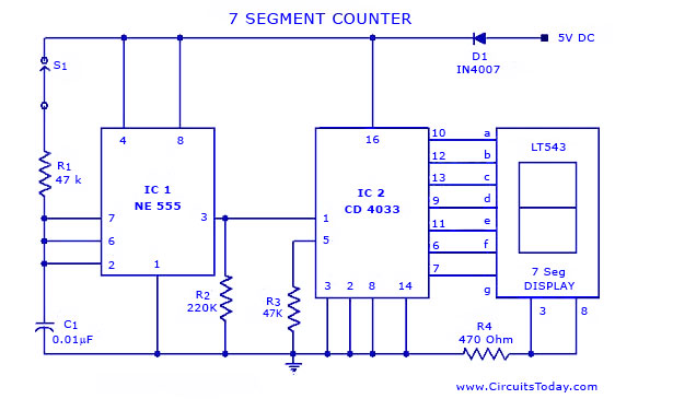
A simple seven-segment counter circuit with an LED display. This counter circuit diagram is designed using the IC CD 4033 as a counter, a 555 Timer IC, and a seven-segment LED display LT 543. The seven-segment counter circuit utilizes the...