
100w inverter circuit

The 100-watt transistor inverter circuit operates by utilizing a combination of bipolar junction transistors (BJTs) to achieve the desired voltage conversion and frequency output. The input from a 12V battery is connected to the base of the first pair of BC558 transistors, which are configured in a push-pull arrangement. This arrangement allows for efficient switching, generating a square wave output. The RC network plays a crucial role in determining the oscillation frequency, which is initially set at 100Hz.
To achieve the final output frequency of 50Hz, the circuit includes a second stage with another pair of BC558 transistors that function as frequency dividers. This division is essential for applications requiring a standard 50Hz output, commonly used in household electrical systems.
The Darlington pair configuration, consisting of the BD139 and 2N3055 transistors, is employed to drive the transformer effectively. The Darlington arrangement enhances the current gain, allowing the circuit to drive the transformer with sufficient power to step up the voltage from 12V to 220V. The transformer is designed as a center-tapped unit, which facilitates the conversion of the square wave signal into an alternating current (AC) output suitable for powering standard appliances.
Overall, this inverter circuit is a practical solution for converting low-voltage DC power into high-voltage AC power, making it useful for various applications, including backup power supplies and portable power systems. The simplicity of the design, utilizing discrete transistors instead of integrated circuits, contributes to its reliability and ease of construction.This is transistor inverter circuit diagram 100watt it sizes are easy circuit. Because of use the all transistor, have no the integrated circuit. It performs to modify from battery 12V be 220V 50Hz signal square wave. By the circuit works with transistor BC558 x 2pcs and RC assemble the circuit produces 100HZ frequency from that time. There is the transistor BC558 2 again, build the circuit divides by 2 times frequency be left 50Hz frequencies from that time. There is the transistor BD139 and 2N3055 each other be Darlington for drive AC transformer 12V CT 12V : 220V, enhance ac voltage 12V from be 220V 50HZ fully be usable next.
The detail is other see in inverter circuit diagram. 🔗 External reference
Related Circuits
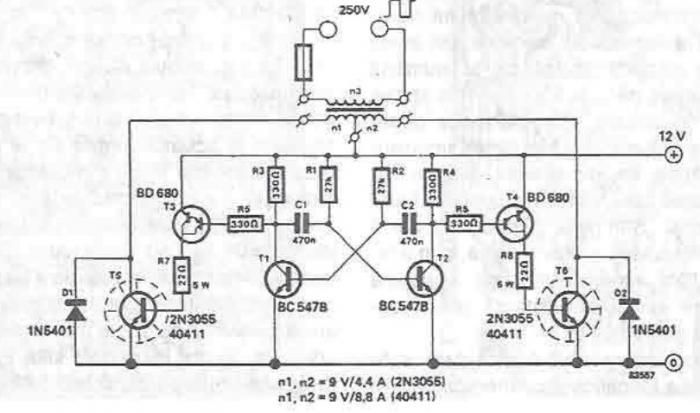
A simple portable converter that transforms 12V to 250V can be constructed using this circuit diagram. This converter is intended for portable use with a 12V car battery. A built astable multivibrator, consisting of transistors T1 and T2, generates...
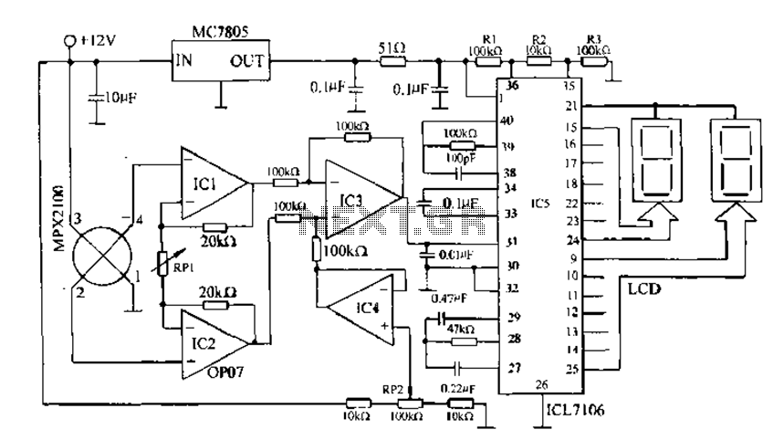
Digital pressure measuring circuit using AD7710/7715/7730 multifunction digital sensor signal conditioning ICs. These ICs integrate a digital interface with the control port, a clock generator, a digital filter, amplitude modulation, a programmable gain amplifier, an A/D converter, and other...
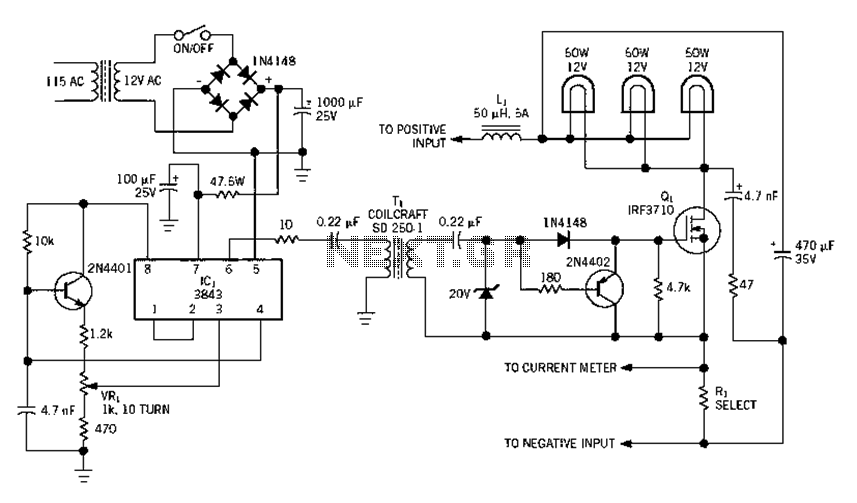
Electrical equipment provided for a power supply circuit design in the power section, as illustrated below. The power supply circuit design is a critical component in various electronic systems, serving as the backbone for powering other devices. The schematic typically...
This article describes a circuit for a simple single-cell lithium-ion battery charger utilizing the LP2391 regulator IC. The circuit presented is designed for charging a single-cell lithium-ion battery efficiently. The LP2391 is a linear voltage regulator that provides a constant...
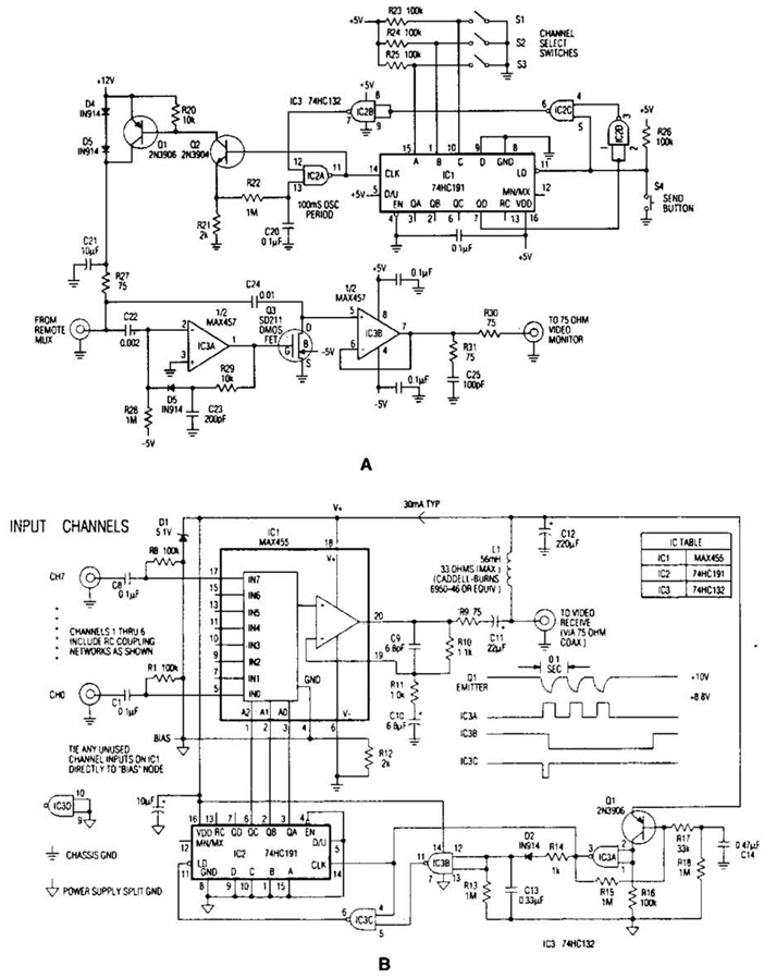
In the video system shown in Figs. A and R, a single coaxial cable transmits power to a remote location, selects one of eight video channels, and returns the chosen signal. This system can select from multiple remote surveillance...
This triac-based 220V AC motor speed controller circuit is designed for controlling the speed of small household motors, such as drill machines. The motor speed can be adjusted by altering the setting of P1, which determines the phase of...