
YUV(YCbCr) to RGB converter
 to RGB converter")
The YUV to RGB converter is an essential circuit for interfacing modern video equipment with legacy displays that lack direct component video input. This converter takes the YUV (or YCrCb) format, which separates luminance (Y) from chrominance (U and V) information, and transforms it into the RGB format used by older monitors and televisions.
The typical architecture of a YUV to RGB converter includes several key components. First, an analog front end is employed to receive the YUV signals. This front end may consist of operational amplifiers configured to buffer and scale the incoming signals to appropriate levels for further processing.
The core of the conversion process is achieved through a series of matrix multipliers. The YUV signals are mathematically transformed into RGB using the following equations:
- R = Y + 1.402 * (V - 128)
- G = Y - 0.344136 * (U - 128) - 0.714136 * (V - 128)
- B = Y + 1.772 * (U - 128)
These equations indicate that the Y component contributes directly to the RGB outputs, while the U and V components are used to adjust the color information. The constant values in the equations are derived from the standard conversion coefficients for the YUV color space.
After the conversion, the RGB signals may require further conditioning to match the voltage levels and impedance characteristics of the target display. This may involve additional amplification stages or filtering to minimize noise and ensure signal integrity.
Finally, the output stage of the converter is designed to drive the RGB inputs of the display device. This can include buffering circuits to prevent loading effects that may degrade the video quality. In some designs, additional features such as sync signal generation may be incorporated to ensure proper timing and synchronization with the display.
Overall, the YUV to RGB converter is a critical component in bridging the gap between modern digital video sources and older analog display technologies, enabling the continued use of legacy equipment in contemporary video applications.Recently, most digital video equipments, such as video recorder, DVD player and TV game, have component video output. The component video signal is like RGB video signal, but it cannot connect to RGB monitor directly. Thus I designed and built YUV(YCrCb) to RGB converter to use old TV monitor or video equipment which does not have component video input.
🔗 External reference
Related Circuits
This high voltage converter circuit begins with a 30-volt power supply and is capable of delivering output voltages ranging from 0 to 3 kV for version 1, or from 0 to 10 kV for version 2. The high voltage converter...
Below is the schematic diagram of an audio input module. This module is capable of producing a DC output voltage that is proportional to the amplitude of the input signal. The audio input module typically consists of several key components...
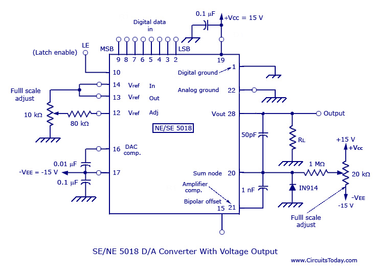
Monolithic and hybrid digital-to-analog converters utilizing MC 1408 IC and SE/NE 5018, including specifications and applications. Digital-to-analog converters (DACs) are integral components in various electronic systems, enabling the conversion of digital signals into corresponding analog voltages or currents. The MC...
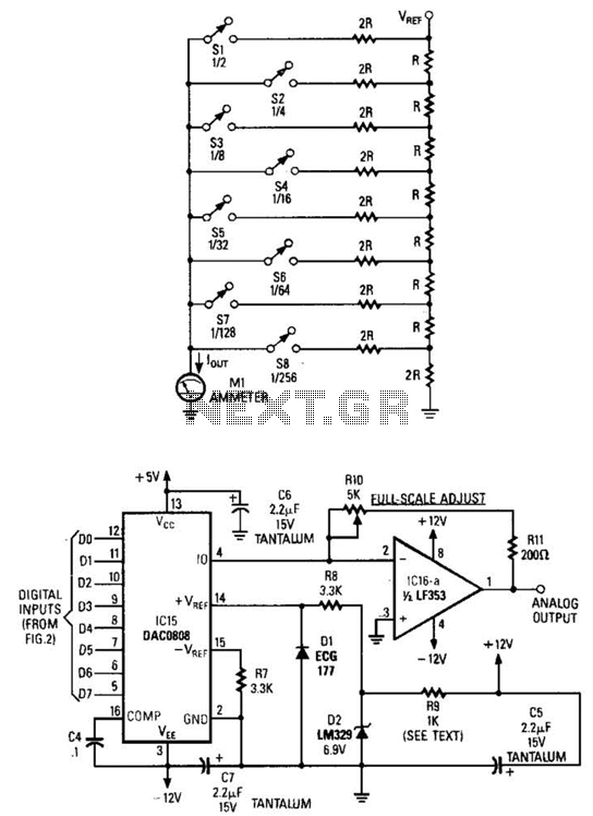
Figure A illustrates an R/2R resistor ladder. Each closed switch increases the current flow. A basic channel A/D converter is depicted in Figure B. The voltage reference (D2) is shared across all channels, although the value of the dropping...

The circuit is designed to convert sinusoidal input signals into TTL output signals and can process input voltages exceeding 100 mV. This circuit typically employs a comparator to achieve the conversion from sinusoidal to TTL levels. The sinusoidal input signal...
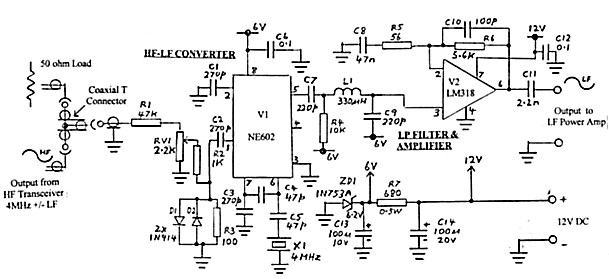
Any mode (e.g., CW, AM, SSB, FSK) initiated in the HF transmitter or transceiver can be regenerated at LF (100 to 200 kHz) using this simple converter. The LF output can drive an LF Power Amplifier. The February 2000...