
ZN414 For AM Receiver

The single-chip AM radio circuit utilizing the ZN414Z integrated circuit (IC) is a compact and efficient design for receiving amplitude-modulated (AM) radio signals. The ZN414Z is a highly integrated device that incorporates multiple transistors within a single package, facilitating a simplified circuit layout while maintaining effective performance.
The circuit typically includes an antenna input, which captures the radio waves, and a tuning capacitor that allows the user to select different radio frequencies. The ZN414Z is designed to operate in the medium wave (MW) band, making it suitable for AM radio broadcasting. The internal architecture of the IC includes a radio frequency amplifier, a detector, and an audio amplifier, enabling the conversion of radio signals into audible sound.
Power supply requirements for the ZN414Z are minimal, often operating within a voltage range of 1.5V to 9V, making it suitable for battery-operated devices. The output stage of the circuit can be connected to a small speaker or headphones, providing a straightforward audio output.
In addition to the basic components, the circuit may include additional passive components such as resistors and capacitors for stability and performance enhancement. Proper layout and grounding techniques are essential to minimize interference and optimize signal reception. Overall, the ZN414Z-based AM radio circuit presents an accessible project for electronics enthusiasts and provides a practical application of radio frequency technology.The circuit diagram of the single chip AM radio. The circuit is designed around the IC ZN414Z which is a ten transistor tuned radio frequency .. 🔗 External reference
Related Circuits
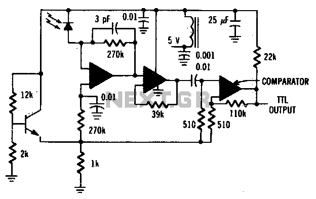
The MFODllOO PIN diode requires shielding from EMI. The MFODllOO PIN diode is a semiconductor device that operates as a switch or rectifier in various electronic circuits. To ensure optimal performance and reliability, it is essential to provide adequate shielding...
This circuit is designed for precise centigrade temperature measurement. It features a transmitter section that converts the sensor's output voltage, which is proportional to the measured temperature, into frequency. The output frequency bursts are transmitted through the mains supply...
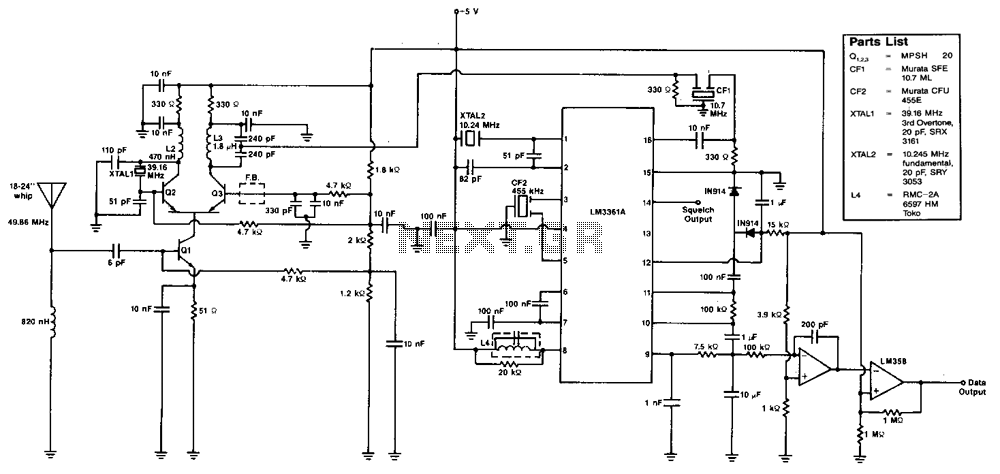
The various signal frequencies are obtained for an incoming carrier centered at 49.86 MHz. The receiver employs double conversion, with intermediate frequencies (i-fs) at 10.7 MHz and 455 kHz. Ceramic filters are used in both intermediate frequencies for selectivity...
The game was originally designed to position three balls locked in holes on a slowly rotating ring around the Deadworld. Once the third ball was secured, a mechanical arm would release them, dropping the balls onto the playfield. This...

Many audio systems consist of separate units, and due to economic reasons, only the amplifier is equipped with a remote control receiver module. In audio system designs where components are split into separate units, it is common for only the...
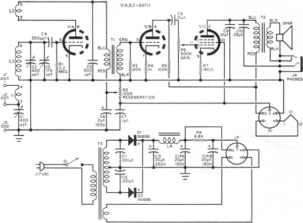
RF Cafe visitor David M. requested the scanning and posting of an article from the January 1963 edition of Popular Electronics, authored by Philip Hatfield from the Receiving Tube Department of General Electric. The article describes a straightforward design...