
zn415 am radio with tda2822m amplifier

The ZN415E integrated circuit (IC) serves as a versatile component in the design of AM radio receivers, providing essential functionalities such as RF detection, amplification, and automatic gain control (AGC) within a single package. This integration simplifies the design process, allowing engineers and hobbyists to produce sensitive and high-quality receivers without the need for extensive external circuitry.
The ZN415E represents an enhancement over its predecessor, the ZN414, primarily through its improved audio output capabilities. The inclusion of an 18 dB buffer stage in the ZN415E allows it to drive headphones and small speakers directly, making it particularly suitable for portable applications where space and power efficiency are critical.
Despite the discontinuation of the ZN41x series by the manufacturer, these ICs remain accessible through various electronic supply channels, ensuring that enthusiasts can still leverage their capabilities in new projects. The existence of alternative ICs, such as the MK484 and TA7642, provides additional options for designers seeking similar performance characteristics in AM receiver applications.
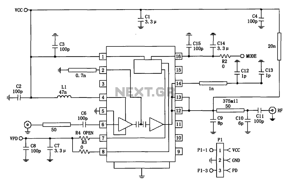
The design of the coil L1 is a crucial aspect of the receiver's performance, as it influences the tuning and sensitivity of the circuit. The specification of 55 turns of 0.315 mm (30 SWG) enameled copper wire on a ferrite rod measuring 10 mm x 100 mm is optimized for AM radio frequencies. However, flexibility in coil design is encouraged, as other AM radio coils can be repurposed from available materials, potentially enhancing the performance of the receiver based on individual project requirements.
In summary, the ZN415E IC and its associated components provide a robust foundation for building AM radio receivers, combining advanced features with ease of use, and maintaining compatibility with existing electronic components.RF detector circuit, RF amplifier circuit, auto gain control circuit (AGC) etc is already built inside the IC due to which you can easily build a high quality and sensitive am receiver using this IC. The ZN415E IC is an advance version of ZN414 IC, the internal circuit and sensitivity of both the ICs are almost same.
The only difference between t he two is the audio output. The upgraded version ZN415E contains an 18 DB buffer stage to increase the audio output to drive headphones and small speakers directly. Although the ICs of ZN41x series has been discontinued by the manufacturer few years back but you can still found them in old stocks at your local electronic stores or online.
There are also other similar versions of ZN414 IC are available like MK484, TA7642 with similar performance. For more details see: Radio & RF Circuits Section. Coil L1: The Coil L1 is equal to 55 turns of 0. 315mm (30 swg) enameled copper wire wound on 10mm x 100mm long ferrite rod. You can also try other AM radio coils you have in scrap. 🔗 External reference
Related Circuits
The VCA project demonstrates the use of the VCA_Setup and VCA_Data components in ADS. These components belong to the ADS behavioral model suite located under the System - Data Models palette. The schematic "Amp_wBothMatches_setup.dsn" is designed to extract circuit-level...
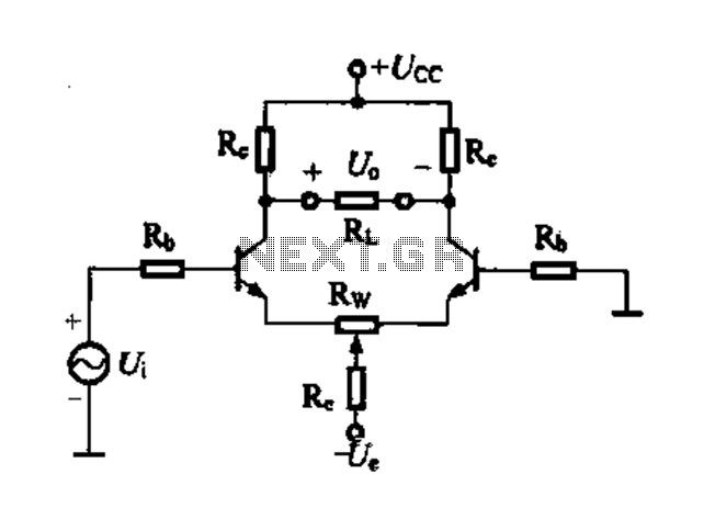
Differential amplifier circuit with four connection methods and characteristics for comparison. The circuit exhibits magnification with a single tube when symmetrical. Additionally, CMRR (Common Mode Rejection Ratio) is adapted from single-ended input to a double-ended output. The differential amplifier is...
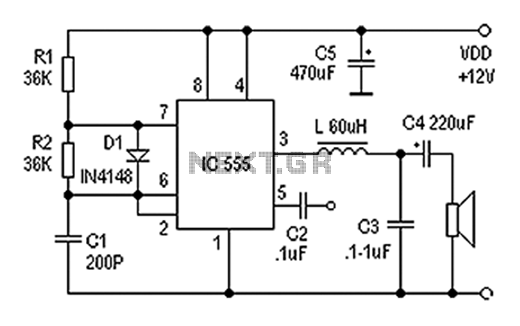
Also known as a digital amplifier, the Class-D amplifier is characterized by its compact size and high efficiency. This circuit utilizes a 555 timer IC to create a Class D amplifier. The 555 timer operates as a controllable multivibrator,...
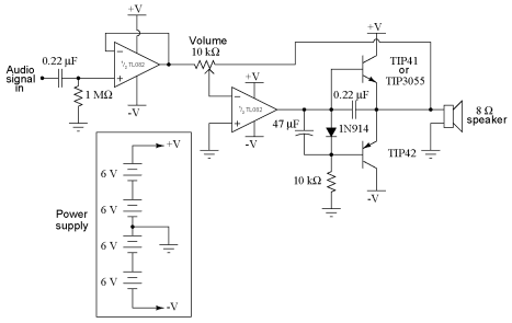
It is advisable to obtain TIP41 and TIP42 transistors, which are closely matched NPN and PNP power transistors with dissipation ratings of 65 watts each. If a TIP41 NPN transistor is unavailable, the TIP3055 (available from Radio Shack) serves...
The circuit utilizes two 2N3819 FETs arranged in a cascode configuration. The lower FET functions in common source mode, while the upper FET operates in common gate mode, achieving full high-frequency gain. The lower FET is tunable, enabling peak...
877 ~ 924MHz RF2152 power amplifier circuit diagram. The RF2152 is a high-performance power amplifier designed for applications in the 877 to 924 MHz frequency range. This amplifier is typically used in various RF communication systems, including wireless networks and...