
ZS100 Connection Signal

The Noisy Regen Receiver is a type of radio receiver that utilizes regenerative feedback to amplify weak radio signals. This circuit is particularly effective in the 27-MHz frequency range, which is commonly used in various remote-control applications, such as model airplanes, cars, and other hobbyist devices.
The primary components of the circuit typically include a radio frequency (RF) amplifier, a mixer, and a detector. The RF amplifier enhances the incoming signal, while the mixer combines the amplified signal with a local oscillator frequency to produce an intermediate frequency (IF). This IF signal is then demodulated by the detector to extract the audio or control signals intended for the remote-controlled device.
The regenerative aspect of the receiver is achieved by feeding a portion of the output signal back into the input stage. This feedback significantly increases the gain of the circuit, allowing it to pick up even weak signals. However, it can also introduce noise, which is a characteristic feature of this type of receiver, hence the term "Noisy Regen."
The circuit may also include various passive components such as resistors, capacitors, and inductors, which are essential for tuning and filtering the signals. The design allows for adjustments to be made to optimize performance based on the specific application, ensuring that the receiver can effectively respond to the desired frequency while minimizing interference from other signals.
Overall, the Noisy Regen Receiver Circuit is a versatile and effective solution for hobbyists and engineers working with remote-control systems, providing a balance between simplicity and functionality in the realm of radio frequency communication.The following circuit shows about Noisy Regen Receiver Circuit Diagram. Features: used in model remote-control systems, 27-MHz superhet receiver .. 🔗 External reference
Related Circuits
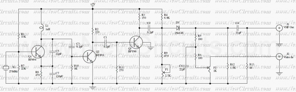
This circuit is a RF modulator which can be used for modulating of video signals. The P1 controls the Light and the P2 controls the contrast of video signal. The RF modulated output signal can be received on the...
This function generator IC is specified to work to 20 MHz. So far, this unit works nicely to 50KHz. Since I seldom need signals higher than that, it has taken up a happy home on my workbench and further...
The limitation of this architecture is that it overlooks the variations among different channels. Initially, the subwoofer channel has a limited bandwidth, and its signal is often produced in real-time by summing the low-frequency components from the full-bandwidth channels....
.png)
The one-touch turn signal (OTTS) module enhances the functionality of the turn signal lever by adding a mode where a single touch makes the indicators blink for a certain number of times. This behavior is also known as lane...

The multi-purpose signal generator circuit consists of integrated circuit oscillators and frequency dividers. It generates square waves ranging from high frequencies to sub-audio frequencies and also produces a frequency standard in the VHF range. The alternative oscillator section feeds...
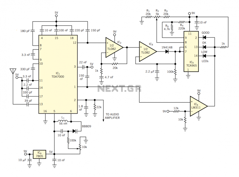
The IC has an FLL (frequency-locked-loop) structure. The filtered output of the FM discriminator frequency-modulates the local oscillator to provide negative-feedback modulation. The result is compression of the signal at the output of the mixer. Thus, the IF bandpass...