
Five uses tri-state logic audio pen CD4066 555
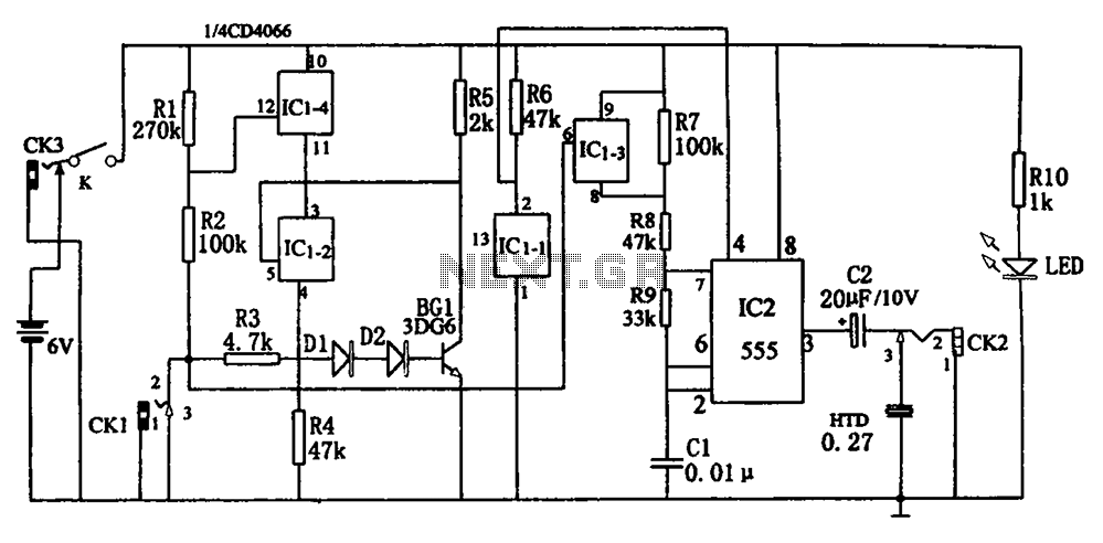
The circuit utilizes a 555 timer configured in astable mode, which generates a continuous square wave output. This output is used to control the four-way switch (CD4066), allowing for the selection between different audio signals or pathways. The CD4066 is a quad bilateral switch that can connect or disconnect four independent signal paths, providing flexibility in routing audio signals based on the state of the multivibrator.
Resistors R7, R8, and R9, in conjunction with capacitor C1, determine the frequency and duty cycle of the oscillation produced by the 555 timer. The values of these components can be adjusted to set the desired operating frequency of the multivibrator, which directly influences the switching rate of the CD4066.
This tri-state logic pen audio circuit is particularly useful in applications requiring dynamic audio signal routing, such as in mixers or effects processors, where multiple audio sources need to be switched seamlessly. The integration of the multivibrator and the CD4066 allows for efficient control of audio pathways, enabling complex audio manipulation without the need for mechanical switches, thereby enhancing reliability and reducing wear over time.As shown in Figure five uses tri-state logic pen audio circuit. The circuit mainly by the multivibrator, four-way switch CD4066 (IC1) circuit with some RC com ponents consisting of other components. Wherein the multivibrator 555 (IC2) and R7, R8, R9, C1 constituted by the oscillation frequency off IC1-3 state control.
Related Circuits
The schematic diagram presented is of a twin "T" phase shift oscillator, an audio oscillator. This oscillator derives its name from the phase shift network formed by resistors R3, R4, and capacitors C1, C2, and C3. This network shifts...
A mixer circuit is being developed. There is uncertainty regarding its functionality, and a request for verification has been made. In this schematic, resistors R1 and R2 are utilized. The mixer circuit typically combines two or more input signals into...
This three-band equalizer circuit is an active filter network designed for bass, midrange, and high audio frequencies. It utilizes the LM833 operational amplifier from National Semiconductors. The output of this three-way graphic equalizer is intended to be DC coupled;...
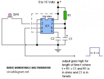
The following circuit illustrates a basic monostable multivibrator, which is based on the 555 Timer IC. Key features include pin 4 functioning as the RESET pin, with the time period defined by the equation t = R1 x C1. The...
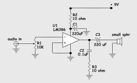
For many applications, there's no substitute for sheer power - low efficiency speakers, outdoor sound systems, or maybe you like the full flavor of the dynamic range of a high power amp. Whatever your requirement, this super power module...
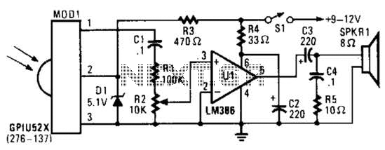
This circuit utilizes an infrared pulse-to-audio converter to assist in troubleshooting infrared remote controls, making it an effective tool for detecting infrared light sources. It employs a photo cell module (Radio Shack P/N 276-137) to detect IR radiation and...