
3 Band Audio Equalizer Circuit
The three-band equalizer circuit employs an active filter configuration, which provides enhanced control over audio frequency response compared to passive filters. The circuit consists of three separate filter stages, each dedicated to a specific frequency range: low frequencies (bass), mid frequencies, and high frequencies. The LM833 op-amp is chosen for its low noise characteristics and high performance, making it suitable for audio applications.
Each band is controlled by a potentiometer, allowing the user to adjust the gain applied to that specific frequency range. The feedback network of each op-amp stage is designed to set the gain and frequency response characteristics. The 100K potentiometers used in the feedback paths introduce slight DC variations, which can affect the overall performance of the circuit. To mitigate any potential issues related to DC offset at the output, a coupling capacitor may be implemented, ensuring that only the AC audio signal is passed to subsequent stages or to the output.
The circuit's maximum equalization capability of 15 dB provides significant flexibility for tailoring audio output to suit different listening environments or personal preferences. The noise attenuation of 90 dB at the middle position of the potentiometer indicates that the circuit is highly effective at minimizing unwanted noise, which is crucial in high-fidelity audio applications. The bandwidth of 1 MHz ensures that the equalizer can handle a wide range of audio frequencies without significant roll-off, maintaining audio quality across the spectrum.
The gain adjustment formula, Vu = R2/R1, allows for precise control over the gain of the circuit, enabling users to customize the equalization effect further. By selecting appropriate resistor values for R1 and R2, the gain can be adjusted to meet specific audio requirements, enhancing the overall versatility of the equalizer circuit. This design is suitable for various applications, including home audio systems, professional sound reinforcement, and musical instrument amplification.This 3 band equalizer circuit is an active filter network for bass, mid and high audio ranges. It is designed around the LM833 opamp from National Semiconductors. The output of this 3 way graphic equalizer is designed to be DC coupled, however due to slight DC variations through the 100K potentiometers at the feedback lines of the opamp A2, a coup ling capacitor might be needed. The maximum equalizer range is about 15 dB. In the middle position of potentiometer, the noise attenuation is about 90 dB with a bandwidth of 1 MHz and a gain of 0 dB. The gain can be changed through R2 using the following formula: Vu = R2/R1. 🔗 External reference
Related Circuits
This design is based on an 18 Watt Audio Amplifier and was developed primarily to address the needs of users who have difficulty locating the TLE2141C chip. It utilizes the commonly available NE5532 Dual IC; however, its power output...

The relay power in the linear circuit is derived from a -120 V bias supply, while the transmit keying output from the Kenwood device is +12 V with a maximum current of 10 mA. A critical component of this...
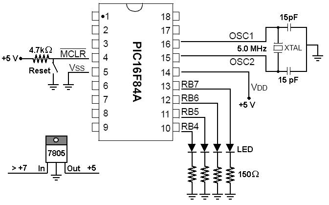
To start working with microcontrollers, several essential items are required. The PICSTART Plus kit, part number DV003001, was purchased from Microchip. This kit contains a sample PIC16F84 microcontroller chip, which in this case is a PIC16F84A chip. This chip...
Grounding the blue wire at the headlamp switch causes the lights to illuminate, indicating a faulty switch. Continuity of the switch has already been verified. The relay consists of two small terminals and two larger ones. The smaller terminal,...
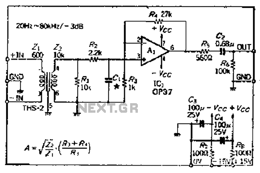
The common mode signal rejection ratio is influenced by the input transformer, which should either be a commercially available or a well-balanced homemade transformer. It is important to note that as frequency increases, the balance may decrease. The transmission...
The protected section of track can be of any desired length and does not need to be equal on both sides of the crossing. The circuit operates bidirectionally and can be linked with other grade crossing circuits to provide...