
Visible-Light Audio Transmitter Circuit
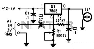
The visible-light transmitter circuit employs a 7805 voltage regulator, which is typically used to provide a stable output voltage of 5V. In this application, it is configured to operate in a variable-voltage mode. This configuration allows the output voltage to be modulated based on the input audio signal. The audio signal, which contains the information intended for transmission, is fed into the common input of the voltage regulator.
As the audio signal varies, it causes corresponding fluctuations in the output voltage of the 7805 regulator. These modulated voltage changes are then used to drive an incandescent lamp. The lamp acts as the transmission medium, emitting light that varies in intensity in accordance with the modulated voltage. This variation in light intensity encodes the audio information, allowing it to be transmitted over a distance.
This method of communication exploits the properties of visible light, making it suitable for applications where radio frequency transmission may be undesirable or impractical. The incandescent lamp's response to the modulated voltage ensures that the transmitted light is directly representative of the input audio signal, enabling effective communication through visible light. In the visible-light transmitter, a 7805 voltage regulator is connected in a variable-voltage configuration, and an audio signal is fed to the common input, to modulate the output voltage. The modulated output voltage is used to transmit intelligence via an incandescent lamp. 🔗 External reference
Related Circuits
AM Transmitter. It is illegal to operate a radio transmitter without a license in most countries. This circuit is deliberately limited in power output. An AM transmitter is designed to modulate an audio signal onto a carrier wave for the...
This circuit is sourced from a remote control tarantula transmitter that operates at a frequency of 49.86 MHz. The schematic is also available on the FCC website by searching for the FCC ID. This device complies with Part 15.235...

This converter shifts frequencies from 10 kHz to 150 kHz up to 4.01 to 4.15 MHz, suitable for use with a shortwave receiver for very low frequency (VLF) reception. A 4 MHz local oscillator frequency is utilized, and the...
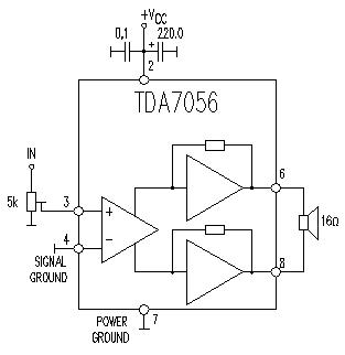
This TDA7056 power audio amplifier circuit diagram project is designed to deliver a maximum output power of 1 watt into an 8-ohm load when powered by a 6-volt supply, or a maximum output power of 3 watts into a...
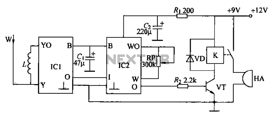
A circuit for an inductive burglar alarm is derived from a radio scanning detection circuit, which includes a signal processing circuit and an alarm circuit. The radar detection circuit module consists of components such as microwave emission, low-pass filtering,...

The circuit employs a field-effect transistor (FET) at the input of a Schmitt trigger, allowing the use of a low-value capacitor. The trigger, controlled by Q1 and O2, exhibits a hysteresis of approximately 3V, regulated by a 3V zener...