
FM by a timer ME555 circuit

The NE555 timer is a versatile integrated circuit used for generating precise timing and oscillation. In this application, it operates as a multivibrator, wherein the charging current influences the output frequency. The circuit configuration allows for frequency modulation by altering the charging time, which is directly influenced by the resistors R1 and RRP1.
The current mirror circuit, composed of transistors VT1 and VT2, plays a crucial role in maintaining a consistent charging current. This is essential for stabilizing the oscillation frequency of the NE555 timer. The current mirror ensures that the current flowing through R1 and RRP1 is mirrored accurately, allowing for predictable changes in frequency modulation based on the input signal.
The low-frequency modulation signal applied to the bias current IB allows for dynamic adjustments to the output frequency of the NE555. This modulation can enable various applications, such as tone generation or signal processing, where frequency variability is necessary. The inclusion of a current Miller circuit in the tube configuration further enhances the circuit's ability to manage and utilize the current effectively, providing additional control over the modulation process.
Overall, this circuit design exemplifies the integration of a NE555 timer with a current mirror and modulation capabilities, showcasing its applicability in electronic signal generation and manipulation.The figure is composed by a NE555 and other withered frequency circuit by changing the self-excited multivibrator NE555 charging current to frequency modulation. The circuit is VT1 and VT2 constitute a current mirror circuit, the charging current can be generated in the charging circuit, the current size is determined by R1 and RRP1. Low frequency modulation signal superimposed to the bias current IB after the oscillation frequency changes. Try to use the current Miller circuit on the tube.
Related Circuits
A larger version of the circuit diagram can be accessed by clicking here. The circuit was created using Eagle from CadSoft, which is a free schematic and PCB layout software for small non-commercial projects. The core component of the...
Open and short circuit tests on a transformer are conducted to determine the equivalent circuit of the transformer, assess its voltage regulation, and evaluate its efficiency. The open circuit test is performed by applying the rated voltage to the primary...
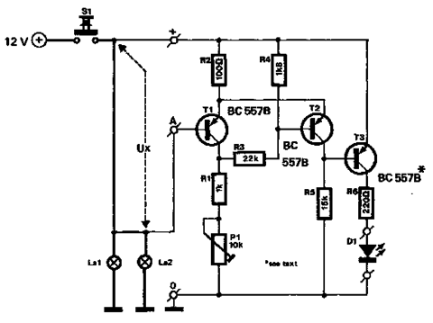
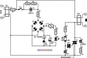
This timer was designed primarily to switch off a portable radio after a set period. This feature allows users to fall asleep on the beach or in a hammock, knowing that the receiver will automatically turn off after a...
The circuit described below monitors the car's brake lights and indicates their operational status using a 12V light-emitting diode (LED). This functionality can prevent fines for driving with defective brake lights and enhance road safety. The monitor relies on...
The following circuit illustrates an Automatic Light Dimmer Circuit Diagram utilizing a 1N4007 diode. Features include integration within a wall-mounted box. The Automatic Light Dimmer Circuit is designed to adjust the brightness of a light source automatically based on ambient...
The vacuum tube remains relevant and functional in certain applications, such as in this continuous wave (CW) transmitter. The circuit is constructed in a traditional breadboard style on a wooden base. Old table radios serve as a valuable source...