
A house automatically fill light circuit
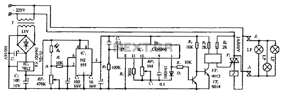
The circuit design is structured into three distinct sections: the light control section, the time control section, and the power supply section, each serving a specific function to ensure the overall operation of the system.
The light control section employs a photoresistor (Rg) and an adjustable resistor (RP) to monitor ambient light levels. During daylight, the low resistance of Rg allows for a higher voltage at point A, leading to a low output signal from pin 3 of the integrated circuit (IC). Conversely, as light diminishes, the resistance of the photoresistor increases, causing a drop in voltage at point A. When this voltage falls below 4V, the IC outputs a high signal, which is then processed through a filtering capacitor to control the lighting system.
The time control section is powered by the light control circuit and features an integrated circuit configured as a binary counter and oscillator. The oscillator's frequency can be adjusted by changing the value of the variable resistor (RP2), which directly influences the timing of the output pulses. These pulses are essential for controlling the duration for which the lights remain on. The output signal from the IC is routed through a diode to halt the oscillator's operation while simultaneously activating a transistor (VT) that controls the lighting circuit.
In the power supply section, a transformer is used to step down the voltage, which is then converted to a steady DC output using a full-bridge rectifier and filtering capacitors. This ensures that the circuit receives a stable 12V power supply necessary for reliable operation.
The overall circuit is designed to provide automated lighting control based on ambient light levels, with a timed delay feature to ensure that the lights turn off after a predetermined duration, effectively managing power consumption and enhancing convenience. Circuit consists of three parts is light-control section 5: Two foot f light time control section; the third is the implementation part of dry i power supply section. JCz (NE55 5) Dry Il photoresistor Rg. J transfer resistance RP, resistor R, capacitor C composed of light Zhu circuit. When the light is strong during the day, Rg2.f low resistance, photosensitive resistance Rgfll adjustable resistor divided voltage point A is high, the pAIC2 section (3) pin output low; when f according weakened, photoresistor resistance value by twenty Tsang Tai Po, partial pressure value at point a gradually decreased, when the voltage at point a is lower than half the power supply voltage (less than 4V), integrated circuit Ic {flip, which (3) BW output high (approximately equal to the supply voltage), the outputs after filtering capacitor c time control lights as part of the power supply. Circuit resistor Ri and capacitor C, is the interference of H {, when the light control circuit to prevent lightning night I caused interference.
JCi, R ,. c, RP etc. pry lamp time juvenile system part, which power is supplied by the light booth circuit, as one of the principle is that when the power is turned on, the integrated circuit IC. Circuit is composed cleared TF c, R7 begin work ashamed, rca is I4 grade serial carry-bit binary counting din/divider and oscillator.
It (9) a (ll) feet have connected capacitor C, adjustable resistance and resistance R. R P2 composition oscillation circuit, change the value RPz can change the frequency of the oscillator, so when the coup delay between the oscillator the output pulse signal by I4 fractions after the frequency output from the IC] foot section (3). This signal, on the one hand through the diode D, so that stops the oscillator, IC; A is maintained at a high electrical output state on the other hand by the resistance scale, to the transistor VT enforcement and other servants of the banking circuit, the lights turned off.
From IC, began to work to put on hold this time it is turned on to light up the work of l knot Cambodia word. Optical gate tuner 4N25, triac vs. AC then delete a contact to switch execution circuit. When the light control circuit ashamed dark because the light H 1 for start output high, the operating voltage of the transistor V t get well by resistors R4 provide bias Luk it saturated conduction, AC contactor is energized units.
Its normally open contact. J closed sets, chicken station fill Wherever light work when the work. after a given time by the delay in lcz knot Cambodia, 3) feet high output wells insurance holds,: V Ti newspaper tube saturated conduction, the collector electric melon brand scoop about 0.2V, the transistor vrz by the memory chicken cut into saturated Park station lights turned off, stopping Ik fill light. AC power transformer T secondary output voltage by the full-bridge rectifier, capacitor filter, lcl steady pressure, this machine provides 12V power supply.
Related Circuits
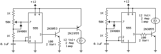
The schematic diagram illustrates a 12 Volt Car Lamp Dimmer Circuit Design utilizing a 555 Timer. This circuit can be employed to dim a standard 25-watt lamp. The 12 Volt Car Lamp Dimmer Circuit utilizes a 555 Timer in astable...
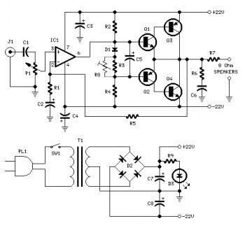
Proper grounding is essential for eliminating hum and ground loops. Connect the ground terminals of J1, P1, C2, C3, and C4 to the same point. Connect C6 to the output ground. An audio amplifier is an electronic device that...
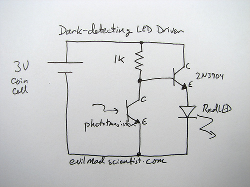
The following circuit illustrates a simple and inexpensive dark-detecting LED circuit. Features include the use of photoresistors, specifically a photocell or LDR, and an LED. This circuit utilizes a light-dependent resistor (LDR) as the primary sensing element. The LDR exhibits...
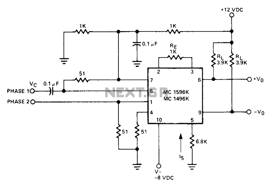
The circuit involves a Signetic balance modem connection utilizing a transistor array as a phase detector. It provides information about the cosine of the phase angle, which corresponds to the frequency of the input signal combined with the integrated...
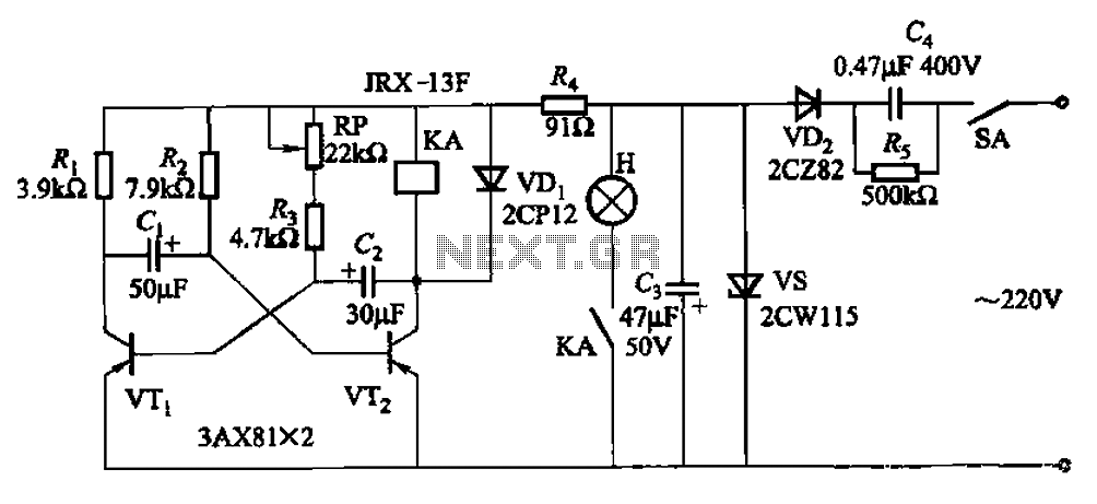
The circuit features a self-excited multivibrator composed of transistors VTi and VTZ. It includes an adjustment potentiometer RP and two RC networks that influence the transistors' parameters, specifically the timing for light activation and deactivation. The described multivibrator circuit utilizes...
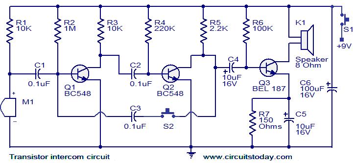
This document describes a simple yet effective intercom circuit that is entirely based on transistors. The design features a three-stage RC coupled amplifier. When the pushbutton S2 is activated, the amplifier circuit, which includes transistors T1 and T2, functions...
Warning: include(partials/cookie-banner.php): Failed to open stream: Permission denied in /var/www/html/nextgr/view-circuit.php on line 713
Warning: include(): Failed opening 'partials/cookie-banner.php' for inclusion (include_path='.:/usr/share/php') in /var/www/html/nextgr/view-circuit.php on line 713