
Two motor speed control circuit and the main level indicating circuit
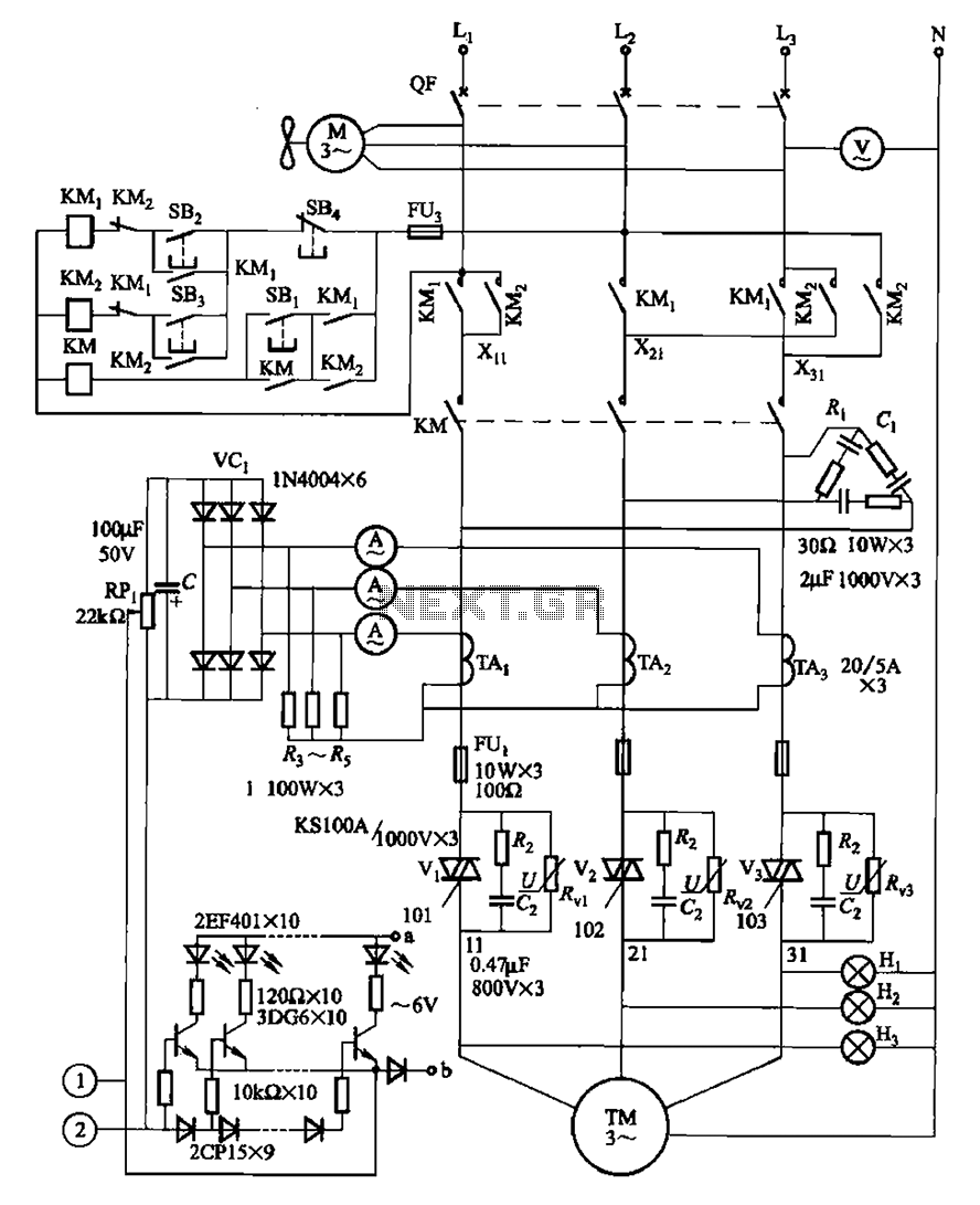
The circuit for the continuous casting machine motor speed control incorporates several key components that work together to ensure efficient operation. The main circuit is responsible for the overall power distribution and control of the motor. It typically includes a power supply, motor driver, and safety features to protect against overloads or faults.
The trigger circuit plays a crucial role in initiating the motor operation. It can be activated manually or automatically, depending on the requirements of the casting process. Manual control allows for direct operator input, enabling adjustments based on real-time conditions. In contrast, the automatic control signal circuit utilizes feedback from various sensors to optimize motor performance without human intervention.
The level indicator is an important component, providing visual feedback on the operational status of the casting machine. It monitors parameters such as motor speed and torque, ensuring that the system operates within designated limits. This information can be critical for maintaining product quality and preventing equipment damage.
In summary, the motor speed control circuit for the continuous casting machine is a sophisticated system that integrates multiple elements to achieve reliable and efficient operation. The combination of manual and automatic controls, along with feedback mechanisms, enhances the overall performance and safety of the casting process. Circuit shown in Figure 3-178. It withered speed torque motor for continuous casting machine, the circuit from the main circuit, trigger circuit, manual and automatic control s ignal circuit and the level indicator and other components. O casting machine motor speed control circuit and the main level indicating circuit (Figure 3-178)
Related Circuits
The sustain pedal, also known as the damper pedal, sends a controller value of CC64 when operated. Pressing the pedal results in an output value of 127, while releasing it results in an output value of 0. Tone generators...
A high voltage power supply DC converter that operates between 3V to 500V has been suggested for use with Geiger tubes. However, during simulation, the output remained at nearly 9V, which matches the input voltage. The schematic drawn has...
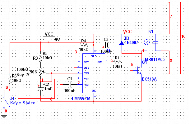
The 555 Timer has extensive applications in electronics. This document describes the use of the 555 Timer in a monostable multivibrator configuration to trigger a transistor driver that energizes a relay, which in turn operates a 230V AC lamp...
This is a beta release schematic. Use at your own risk. The idea is to add this circuitry to a board that already has RAM at address 2000 and an 82C55 I/O chip to provide ports A, B, and...
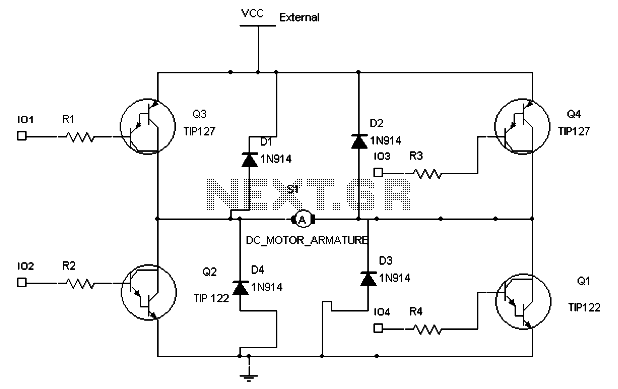
To maintain a constant speed of the motor under varying load conditions, a control application circuit is required. An H-Bridge circuit can be utilized to manage both the speed and direction of the motor. The accompanying diagram illustrates the...
This lie detector circuit diagram provides two readings: one for challenging questions directed at the subject and another to display the subject's emotional state in general. The emotional states are detected not only by heart rate variations and perspiration...